background image

6

Fiber wool

Ceramic fiber

Blind burner plate 250x250

Burner plate insulation gasket 250x250

ø 180

ø 180

95

T 3

ISO 7/1

T 4

ISO 7/1

H

m m

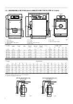
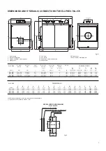
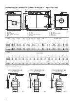
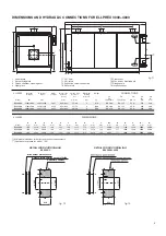
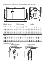
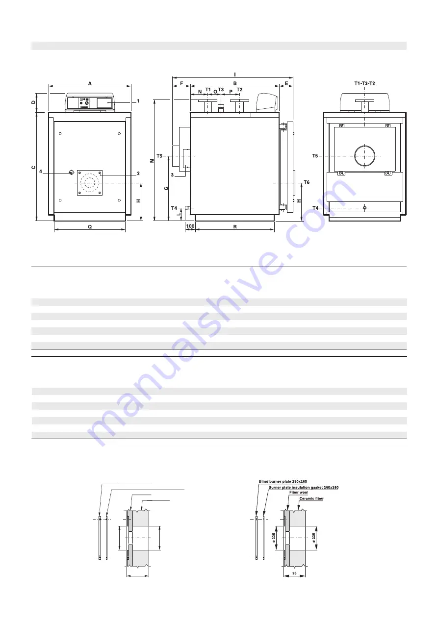
1.3 - DIMENSIONS AND HYDRAULIC CONNECTIONS FOR ELLPREX 170÷630

1

Panel board

2

Burner fixing plate

3

Smoke chamber  cleaning door

4

Sight glass

T1 C.H. flow
T2 C.H. return
T3 Expansion vessel connection
T4 Boiler  drain

T5 Flue socket
T6 Max. burner blast tube dia.

DETAIL FOR DOOR DRILLING

ELL 170÷240

DETAIL FOR DOOR DRILLING

ELL 290÷630

Nominal

Output

kW

130÷170
180÷240
220÷290
255÷340
315÷420
385÷510
480÷630

T 1
T 2

UNI 2278 PN16

T 5

Øi

m m

T 6

Ø

m m

DN 65
DN 65
DN 80
DN 80

DN 100
DN 100
DN 100

Rp 1½
Rp 1½

Rp 2
Rp 2
Rp 2
Rp 2
Rp 2

200
200
250
250
250
250
300

180
180
220
220
220
220
220

ELL 170

ELL 240

ELL 290

ELL 340

ELL 420

ELL 510

ELL 630

ELLPREX

Model

Nominal

Input

kW

140÷186
195÷262
239÷317
277÷371
342÷459
418÷557
520÷688

Water

content

l

190
2 51
2 64
298
3 98
462
565

Water side

pressure

loss(

**

)

m w. c.

0,09÷0,15
0,19÷0,33
0,12÷0,21
0,16÷0,28
0,09÷0,17
0,14÷0,25
0,21÷0,38

9÷15

15÷28
13÷25
17÷34
16÷29
24÷43
32÷55

Smoke side

pressure

loss

mm w. c.

Maximum

working

pressure

bar

6
6
6
6
6
6
6

Weight

kg

435
510
588
629
796
919

1049

ELLPREX

Model

ELL 170

ELL 240

ELL 290

ELL 340

ELL 420

ELL 510

ELL 630

A

m m
820
820
860
860
890
890
890

B

m m
885

1145
1080
1210
1275
1470
1780

1082
1082
1182
1182
1352
1352
1352

C

m m

190
190
190
190
190
190
190

D

m m

139
139
139
139
139
139
139

E

m m

F

m m
190
190
190
190
190
190
190

G

m m
648
648
708
708
748
748
748

380
380
400
400
440
440
440

I

m m

1214
1474
1411
1541
1606
1801
2113

L

m m
130
130
130
130
125
125
125

1210

1210

1310

1310

1485

1485

1485

M*

m m

175
175
215
215
255
255
255

N

m m

130
390
210
340
285
480
790

O

m m

185
185
250
250
315
315
315

P

m m

710

710

750

750

780

780

780

Q*

m m

785

1045

982

1112

1177

1372

1682

R*

m m

(*) Minimum dimensions for boiler room access requirements.
(**) Hydraulic resistance for delta T 15K.

DIMENSIONS

Rp ¾
Rp ¾
Rp ¾
Rp ¾
Rp ¾
Rp ¾
Rp ¾

CONNECTIONS

fig. 2

fig. 4

fig. 3

Summary of Contents for ELLPREX Series

Page 1: ...26739 01 13 rev 4 ELLPREX INSTALLATION USE AND SERVICING INSTRUCTION to be kept by the user...

Page 2: ...boiler house the safety devices the chimney the fuel supply lines the electrical installations and all the other local requirements and safety instructions Approvals The UNICAL boilers ELLPREX range h...

Page 3: ...ter systems BS 5546 Installation of gas hot water supplies for domestic purposes 2nd Family Gases BS 6644 Ventilation for gas appliances of rated input exceeding 60 kW HEALTH SAFETY DOCUMENT No 635 Th...

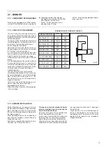
Page 4: ...2 7 3 Burner installation page 15 2 8 Connection of the sight glass to the burner via a cooling line page 16 2 9 Casing assembly page 16 STANDARD PANEL BOARD page 24 3 1 Panel board type 21057 functio...

Page 5: ...by a textile in mineral fiber For models from ELL 4500 to ELL 7000 the outer shell is insulated with a felt lamellar matress thick 50 mm protected by an alumi fig 1 1 2 WORKING PRINCIPLE The ELLPREX b...

Page 6: ...190 251 264 298 398 462 565 Water side pressure loss m w c 0 09 0 15 0 19 0 33 0 12 0 21 0 16 0 28 0 09 0 17 0 14 0 25 0 21 0 38 9 15 15 28 13 25 17 34 16 29 24 43 32 55 Smoke side pressure loss mm w...

Page 7: ...1122 1122 B mm 1605 1800 1995 1432 1432 1432 C mm 190 190 190 D mm 195 195 195 E mm F mm 190 190 190 G mm 765 765 765 H mm 480 480 480 1989 2184 2379 L mm 125 125 125 1540 1540 1540 M mm 298 298 298 N...

Page 8: ...H mm 595 595 640 640 690 690 2346 2686 2781 3151 3225 3545 L mm 180 180 75 75 75 75 1540 1540 1650 1650 1810 1810 M mm 461 461 561 561 661 662 N mm 330 670 510 880 670 990 O mm 500 500 550 550 700 700...

Page 9: ...G mm 1315 1535 1535 H mm 772 915 915 3835 3879 4279 L mm 115 144 144 1990 2271 2271 M mm 325 377 777 N mm 1100 1060 1060 O mm 1330 1280 1420 P mm 1620 1870 1870 Q mm 3200 3164 3564 R mm Nominal Outpu...

Page 10: ...00 3800 5000 4180 5500 4560 6000 4940 6500 5320 7000 3638 3 4838 7 4064 2 5421 8 4446 8 5914 4877 6506 2 5255 3 6989 2 5689 8 7590 5 6012 6012 7058 7058 7909 7909 0 70 0 85 0 80 1 05 0 95 1 15 1 00 1...

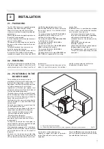
Page 11: ...ion is highly recommended To allow the cleaning of the smoke pipes in front of the boiler a clearance equal to the length of the boiler has to be available With the boiler door opened at 90 the distan...

Page 12: ...the entity of the reinstatement water to avoid inconvenients due to untreated water For that reason it is suggested to fit in the feeding line to the boiler a water meter for small capacities 2 5 2 C...

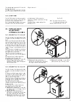
Page 13: ...le A Adjustment in vertical way it is possible only by introducing some washers of convenient thickness under the hinge on which the door rotates fig 17 B Adjustment in transversal way it is possible...

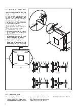
Page 14: ...L H side are normally used as rotating hinges from Right to Left whilst the two ones on the R H side are used as closing hinges Exactly the contrary will happen when the door is hinged on the R H side...

Page 15: ...0 970 270 270 ELLPREX 290 630 220 250 ELLPREX 170 240 180 250 2 7 1 CONFORMITY OFTHE BURNER All the burners equipping the ELLPREX boilers must be CE certificated and must conform to the following dire...

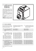
Page 16: ...REX 1850 30001 casing upper part ELLPREX 1850 30002 casing front part ELLPREX 2200 30003 casing rear part ELLPREX 2200 30004 casing upper part ELLPREX 2200 30002 casing front part ELLPREX 2650 30081 c...

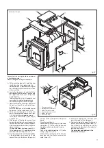
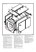
Page 17: ...ion B Locate the side panels 3 and 4 with the lower bend inside the bottom L profiles and the upper bend in the seats of front and rear tube plates To determine which is the left and right panel ensur...

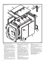
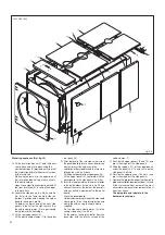
Page 18: ...ht panel ensure that the cable clamp plates are positioned facing toward the front edge Fit the four flathead screws 8 on the inner bend of the rear side panels 3b 4b C Open the combustion chamber doo...

Page 19: ...nd to the upper L profile To determine which is the left and right panel ensure that the cable clamp plates 5 are positioned facing toward the front edge C Open the combustion chamber door and fit the...

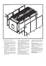
Page 20: ...e side panels 3a 3b 3c and 4a 4b 4c with the lower bend inside the bottom L profiles and hooking the upper bend to the upper L profile To determine which one of the front side panels is the left or th...

Page 21: ...les and hook them to the screws fitted to the upper square tube To determine which one of the front side panels is the left or the right ensure that the cable clamp plates 5 are positioned facing towa...

Page 22: ...thermostat 3 minimum thermostat 4 We recommend that the introduction of the sensors is made up to bottom of the bulb holder s To get a better contact introduce also the arcuated spring 6 and secure th...

Page 23: ...of the two side screws from the panel board rotate its cover towards the front and insert the cables and the capillaries of thermometer and thermostats through the slots on its base Insert the capill...

Page 24: ...een the switching points of the two double pole is 6 C not adjustable Theminimumthermostat accessiblethrough the opening of the panel board cover switches OFF the C H pump during the reacing of the st...

Page 25: ...er and flow are included in the supply the room sensors for the C H systems No 1 and No 2 are optionals The mixing valve and the relevant motor are not supplied by Unical When the room sensor is not f...

Page 26: ...G V 6 6 7 7 8 8 9 9 10 10 2nd stage Tm Minimum thermostat Ts High limit thermostat Vm2 Mixing valve for 2nd zone A Burner lockout warning lamp eventual B Hourmeter eventual 3 5 ELECTRICAL WIRING DIAGR...

Page 27: ...08 RELAY FUNC 1 00 30 C 90 C RELAY TEMP 1 30 C 2K 10K HYST RELAY 1 5K 00 03 RELAY FUNC 2 00 00 01 OFF ON SCREED 00 OFF See explanation SCREED PROGR RETURN Default IV Value range Designation HOTWATER...

Page 28: ...00 24 00 OUT TEMP DEL 1 0K 50K SLOPE OFFSET 5K 00 01 OFF ON B HEAT SINK 01 ON Exit level using RETURN Default IV Value range Designation HEATING CIRCUIT 1 00 04 HC FUNCTION 00 00 03 PUMP MODE 00 5 25...

Page 29: ...ensor code no required after input there is a restart of the controller RETURN end of INSTALLATION Start INSTALLATION Set value Save value and next value Start INSTALLATION Set value Save value and ne...

Page 30: ...02 OPTIMIZAT 00 0 00 3 00 h M OPT TIME 2 00 h 0 00 3 00 h ECONO OPTI 0 00 h 0000 9999 PC ENABLE 0000 Default IV Value range Designation HEATING CIRCUIT 2 MODE 5 C 40 C T ROOM DES 1 20 C 5 C 40 C T RO...

Page 31: ...Mo Tu We TH Fr 06 00 to 22 00 Sa Su 07 00 to 23 00 Value range Designation HEAT CIRCUIT 2 HEAT PROGRAM 1 FACTORY SETTING Mo Tu We TH Fr 06 00 to 08 00 16 00 to 22 00 Sa Su 07 00 to 23 00 HEAT PROGRAM...

Page 32: ...hydraulic schemas shown in the figs 35 36 are principle schemas in case of different system circuits contact please our after sale service dept which will supply you with all the necessary informatio...

Page 33: ...ponsibility of a specialized and well trained burner technician authorised by the burner manufacturer In that occasion a commissioning report has to be filled out POSITION OF THE CORE INSIDE THE TURBU...

Page 34: ...RSTCOMMISSIONING At the commissioning stage of the boiler a qualified technician has to perform the following checks Internal and external sound test of burner and fuel feeding pipe Adjustment of the...

Page 35: ...0 position 5 1 GENERAL RULES Before effecting any operation of cleaning or maintenance disconnect the boiler from the electrical supply acting on the main switch onto the panel board In case of failur...

Page 36: ...ty and control devices imposed by local requirements that cannot be attributed to the constructive geometry and or to the materials used and to the constructive technique and therefore they are not co...

Page 37: ...37 Notes...

Page 38: ...38 Notes...

Page 39: ...39 Notes...

Page 40: ...Unical AG declines any liability for the inaccuriaces that may appear due to errors in trascription or printing It also reserves the right to introduce those modifications to its products that it con...

Reviews: