32
Service info
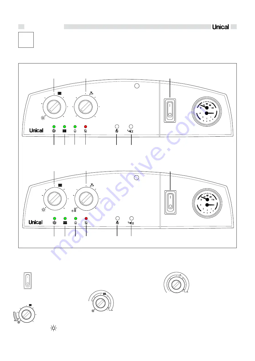
fig. 35
B
D
A
C
E
F
G
H
L
IVEN 04 CTN 24 F - IVEN 04 CTFS 24 F - IVEN 04 CTFS 28 F
B
D
A
C
E
F
G
H
L
IVEN 04 RTN 24 - IVEN 04 RTFS 24 - IVEN 04 RTFS 28
ON / OFF switch (A)
- With the switch in the
I
position
the electrical supply is ON
-
With the switch in the
0
posi-
tion the electrical supply is OFF
Summer/Winter C.H.
temperature control (B)
You can select which mode to
use by turning this knob.
If the knob is in the following po-
sition – – it indicates that
the boiler is working only for do-
mestic hot water production
and that the temperature can
be adjusted turning knob
''C''
.
If the knob is set within the ran-
ge indicated by the arrow on
the illustration it means that the
boiler always gives priority to
the production of domestic hot
water (if it is requested) and
controls the temperature of the
water of the heating circuit from
a minimum of 45°C to a maxi-
mum of 78°C.
D.H.W. temperature control
(C) (Only for IVEN CTN/
CTFS)
If the knob is set within the
range indicated by the arrow
on the illustration it means is
possibile to adjust the dome-
stic hot water temperature.
The temperature can be con-
trolled from a minimum of
35°C to a maximum of 57°C.
MAX
MIN
MAX
MIN
MAX
MIN
MAX
MIN
MAX
MIN
®
IVEN
04
MAX
MIN
MAX
MIN
®
IVEN
04
A
=
On / Off switch
B
=
Summer / Winter C.H. tempe-
rature control
C =
D.H.W. temperature control (+ Antifrost
protection
USERS' INSTRUCTION
3.1 - CONTROL PANEL
3
of an eventual external storage tank IVEN RTN -
RTFS)
D =
Power on lamp (green)
E
=
C.H. request lamp (green)
F
=
Burner on lamp (green)
G =
Burner lockout warning lamp (red)
H =
Chimney sweeper push button
L
=
Reset button
Summary of Contents for EVE 05 CTFS 24 F
Page 35: ...35 ...


