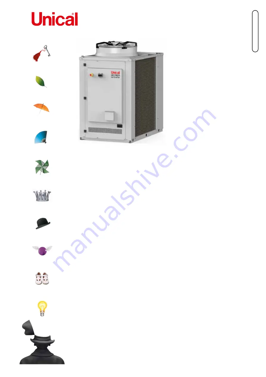
background image

INSTALLATION AND SERVICING MANUAL

ENGLISH

HP_OWER

500 RK - 700 RK - 500 RK A400 - 700 RK A 400

Summary of Contents for HP OWER 500 RK

Page 1: ...INSTALLATION AND SERVICING MANUAL E N G L I S H HP_OWER 500 RK 700 RK 500 RK A400 700 RK A 400 ...

Page 2: ...ING AND MINIMUM TECHNICAL CLEARANCES 11 5 5 DIMENSIONs 13 5 5 1 Standard version 13 5 5 2 Version with tank kit 13 5 6 CENTRE OF GRAVITY AND DAMPERS LOCATION 14 5 7 ACCESSING THE INNER PARTS 15 5 7 1 Access to the inside of the unit on the electrical panel side 15 5 7 2 Access to the inside of the unit on the hydronic kit side 16 5 8 Plumbing connections 16 5 8 1 Features of the circuit water 17 5...

Page 3: ...OMMISSIONING 28 11 RESIDUAL RISK 29 12 TECHNICAL DATA 33 12 1 TECHNICAL SHEET HEAT PUMP 33 12 2 UNIT AND AUXILIARY ELECTRICAL DATA 35 13 OPERATING LIMITS 38 13 1 EVAPORATOR WATER FLOW RATE 38 13 2 COLD WATER PRODUCTION SUMMER MODE 38 13 3 HOT WATER PRODUCTION WINTER MODE 38 13 4 AMBIENT AIR TEMPERATURE AND SUMMERISED TABLE 38 14 USER INTERFACE CONTROLLER 41 14 1 MENU 42 14 2 SETPOINT MENU 42 14 3 ...

Page 4: ...the installed unit The user is recommended to follow the instructions contained in this booklet especially those concerning safety and routine maintenance 1 1 HOW TO KEEP THE MANUAL The manual has to always be kept together with the unit it refers to It has to be stored in a safe place away from dust and moisture It must be accessible to all users who shall consult it any time they are in doubt on...

Page 5: ...nd maintenance which the user is expected to carry out on the unit cannot be done by children without supervision Direct interaction with the device by people with electrically controlled medical devices such as pacemakers is forbidden as harmful in terference may be created It is recommended to keep adequate distance from unit installation as indicated by the medical system used Users of electric...

Page 6: ... European zone Among the provisions of this regulation it sets forth that operators working on systems running with greenhouse gases be in possession of a certification issued or acknowledged by the competent authorities attesting that they have passed a test authorising them to perform this work In particular Up to 3kg total refrigerant in the appliance category 2 certification 3 kg e and more to...

Page 7: ...ratory protection mask and eye protection goggles should be used during cleaning operations 4 3 SAFETY SIGNS The unit features the following safety signs wich must be complied with Generic hazard Dangerous electric voltage Moving parts Surfaces wich can cause injuries Boiling surfaces wich can cause burns Fire hazard ...

Page 8: ... aspiration d air soient suffisants dans les locaux de travail conseils pour une utilisation sûre Ne pas respirer de vapeurs et ne pas utiliser d aérosol Stockage Fermer soigneusement et conserver dans un endroit frais sec et bien ventilé Conserver dans les récipients originaux Produits incompatibles explosifs matériaux inflammables Peroxyde organique CONTRÔLE DE L EXPOSITION PROTECTION INDIVIDUEL...

Page 9: ...near the unit No smoking near the unit Transport and storage must be performed in accordance with the national regulations in force Specifically according to ADR provisions the total maximum quantity by transport unit in terms of net mass for flammable gases is 333 kg 5 INSTALLATION CAUTION All the operation described below must be done by QUALIFIED PERSONNEL ONLY Before any operation on the unit ...

Page 10: ...ng coils The aluminium fins are very sharp and can cause serious injuries After the maintenance operations close the panels by fixing them with screws 5 2 TRANSPORT AND STORAGE LIMIT TEMPERATURE Minimum transport storage temperature C 10 C Maximum transport storage temperature C 50 C 5 3 LIFTING AND HANDLING The handling must be performed by qualified personnel properly equipped with appropriate t...

Page 11: ...ossible overturning The support plane mustn t be smooth to avoid water ice depoisit as potential sources of danger Unit installation place must be free from foliage dust etc which could clog or cover the coil Installation in areas subject to water stagnation or fall for example from gutters should be avoided Also avoid areas subject to snow accumulation such as corners of buildings with sloping ro...

Page 12: ...tance be tween them is 2200 m L min Covering with canopies or placing near plants or walls should be avoid ed to prevent air circulation In the event of winds stronger then 13 9 17 1 m s the use of wind barriers is recommended We always invite you to make an environmental impact assessment based on the power and sound pressure data shown in chapter Technical data and the sound emission limits base...

Page 13: ...IONS 5 5 2 Version A400 with tank kit Dimensions A Lenght mm 1850 B Depht mm 1110 C Height mm 1920 IN OUT inch 1 1 2 Grooved E Power supply input Dimensions A Lenght mm 2460 B Depht mm 1110 C Height mm 1920 IN OUT inch 1 1 2 Grooved E Power supply input ...

Page 14: ...tandard with integrated pump 1110 1754 652 517 With tank kit A 400 1110 2365 970 540 HP_OWER 700 RK Standard with integrated pump 1110 1754 683 511 With tank kit A 400 1110 2365 979 533 Model Version HP_OWER 500 RK HP_OWER 700 RK Standard with inte grated pump Shipping weight kg 535 595 Operating weight kg 540 600 With tank kit A 400 Shipping weight kg 685 745 Operating weight kg 1090 1150 The ide...

Page 15: ... located on the front side where the electrical panel is also located To unlock it it is necessary to unscrew the fixing screws using the appropriate tool and pull it towards you using the handle located under the panel Pay attention to the electrical panel which is bound to the door itself For access to the panel see the relative chapter The operator must pay attention to the fins of the driver w...

Page 16: ...d exhaust valve where necessary CAUTION When sizing the pipes make sure not to exceed the maximum pressure drop on plant side reported in the techni cal data table see useful head CAUTION Connect the pipes to their fittings always using the key to key method CAUTION Create a suitable drain for safety valve CAUTION The expansion vessel if present on the unit check the hydraulic diagram has a limite...

Page 17: ...en content 0 1 ppm Max glycol quantity 40 Phosphates PO4 2ppm Manganese Mn 0 05 ppm Iron Fe 0 3 ppm Alkalinity HCO3 70 300 ppm Chloride ions Cl 50 ppm Sulphate ions SO4 50 ppm Sulphide ions S Nessuno Ammonium ions NH4 Nessuno Silica SiO2 30 ppm 5 8 2 Hydraulic diagram inside the unit The hydraulic connection diagrams to the unit for all the available versions and the legend valid for all the diagr...

Page 18: ...18 STANDARD HYDRONIC CIRCUIT EV CO W IN P DV VSI W OUT W IN WF WF HKA2 HKA1 RV AV AV FC BV HYDRONIC CIRCUIT VERSION AC 400 ...

Page 19: ...need to install drainage systems CAUTION for heat pump units in the event that the prepared ducting system is not used a limited amount of water possi ble ice in the winter period from the condensate drainage system may be deposited in the vicinity of the unit with conse quent danger of slipping falling 5 8 3 Filling Discharge of the plant CAUTION Supervise all filling top up operations CAUTION Be...

Page 20: ...xchange output The device also features a safety function because in the event of exchanger breakdown it allows the refrigerant gas to escape outside preventing it fro being conveyed to the internal terminals The valve can be kept in a closed position by closing the plug on the drain by loosening the plug the valve remains in open position and air is discharged automatically If you notice a water ...

Page 21: ...technical characteristics table Use a dedicated power line do not power the appliance through a line to which other users are connected Fasten the power cables securely and make sure they do not come into contact with sharp corners Use double insulated cables with copper wires The ground connection must be carried out first during the connection phase vice versa it must be removed last when the un...

Page 22: ... Remote on off unit close unit on open unit off Voltage free digital input XC2 1 2 2 Remote summer winter mode change input to activate the function see the relative para graph in the MCO manual Voltage free digital input XP10 1 10 2 DHW valve control to activate the function see the relevant section in the MCO manual Voltage output 230Vac 50Hz 2A AC1 XPE 1 1 1 2 Alarm signalling to activate the f...

Page 23: ...2 1 2 2 2 2 2 1 3 1 3 2 3 2 3 1 4 1 4 2 4 2 4 1 5 1 5 2 5 2 5 1 6 1 6 2 6 2 6 1 7 1 7 2 7 2 7 1 8 1 8 2 8 2 8 1 9 1 9 2 9 2 9 1 10 1 10 2 10 2 10 1 L3 1 L3 1 L3 2 L3 2 L3 3 L3 3 N1 N1 N2 N2 N3 N3 PE1 PE1 PE2 PE2 PE3 PE3 L1F1 L1F1 L1F2 L1F2 L1F3 L1F3 D 1 D 1 D 2 D 2 LP1 1 LP1 1 LP1 2 LP1 2 LP1 3 LP1 3 LP2 1 LP2 1 LP2 2 LP2 2 LP2 3 LP2 3 I G e n o i s n a p s E e s a B Espansione GI Base Morse era d...

Page 24: ...GING ATTACHMENT PED TR 1 LOW PRESSURE TRANSDUCER F 1 FILTER DRIER PSH HIGH PRESSURE SWITCH HC 1 2 CRANKCASE RESISTANCE HKA 1 HEAT EXCHANGER ANTIFREEZE RESISTOR AF 1 AXIAL FAN TE SD 1 2 3 SUCTION TEMPERATURE PROBE RD SUCTION LINE TE DT 1 2 EXHAUST TEMPERATURE PROBE RD RS SUPPLY SUCTION LINE TE DS 1 TEMPERATURE PROBE DS RL LIQUID LINE TE EXT 1 OUTDOOR AIR PROBE RS SUCTION LINE RS RD SUCTION DELIVERY...

Page 25: ...not to immediately terminate the warranty CAUTION Summer winter operation must be selected at the start of the relative season Frequent and sudden changes of this operation must be avoided so as not to damage the compressors CAUTION Upon initial installation and start up make sure that the machine works properly both in heating and cooling mode 6 1 SWITCHING ON THE UNIT To supply power to the mach...

Page 26: ...s CAUTION It is possible that a certain quantity of oil from the compressor is deposited in the pipes of the refrigeration circuit especially by bends In case of maintenance operations in which it is necessary to unsolder the pipes it is strongly recom mended to proceed with the cutting of the same and not with the desoldering with a torch as the flame triggers any oil present It is prohibited to ...

Page 27: ...instructions below Remove any superficial filth Debris such as leaves fibres etc must be removed without a vacuum cleaner use a brush or another soft tool carefully avoiding scratching with metal or abrasive parts If you use compressed air pay attention to keep the air flow perpendicular to the surface of the coil in order not to bend the aluminium fins Pay attention not to bend the fins with the ...

Page 28: ... liquid gas water can increase the weight Consult the table before the maintenance phase or refer to the label of the component itself and choose the equipment posture most suitable for the work to be carried out taking into account the load limits imposed by the technical standards and the state of health and ability of the worker himself Weight kg Component HP_OWER 500 RK HP_OWER 700 RK Compress...

Page 29: ...e instability of the unit during handling The procedures for correct unit handling and installation are indicated on the user installer manual under chapter 5 with in dication of the center of gravity of the lifting points and equip ment Protection devices use is also recommended as required by current regulations Failure by the installer to comply with the installation procedures X X Mechanical c...

Page 30: ... techni cian or irresponsible behavior by the user X X Electrical effects on medical implants pacemakers caused by electromagnetic phenomena The user installer manual in chapter 3 states the prohibition of direct interaction with the unit by people with electrically controlled medical devices such as pacemakers It is recommend ed to keep a distance from the installation site of the unit as indicat...

Page 31: ...with the in structions given in the manual X Generated by materials substances burn scald from escaping refrigerant The safety measures to be adopt ed in case of maintenance clean ing or control of the unit and the personal protective equipment to be equipped are indicated in the user installer manual under chapter 9 Failure to comply with the in structions given in the manual X X Generated by mat...

Page 32: ...r chapter 9 contains specific warnings on maintenance and cleaning to be carried out on the surfaces of the sheets and heat exchange coils The technical bulletin provides advice on the treatments to choose based on the environmental conditions Failure to comply with cleaning and maintenance and or incor rect assessment of the atmo spheric agents that characterize the installation site X X Generate...

Page 33: ...cated refers to the total required the designer must meet it considering the quantity already present inside the unit depend ing on the hydronic kit chosen please check this value in the data sheet 9 Sound power condition 3 value determined on the basis of measurements made in accordance with UNI EN ISO 9614 1 in compilance with the requirements of Eurovent certification 10 Sound pressure value ca...

Page 34: ...ntity in tonnes of CO2 equivalent 7 ton 6 4 8 1 Design pressure high low heat pump mode bar 46 27 6 Design pressure high low chiller mode bar 46 27 6 External zone fans Type EC Quantity 1 Nominal power 1 kW 1 95 3 1 Maximum power input kW 1 95 3 1 Maximum current input A 4 8 4 8 Nominal air flow L s 5431 5547 Internal heat exchanger Internal heat exchanger type A piastre BPHE N internal heat excha...

Page 35: ...rs due to contamination of the internal gas water exchanger are shown below Description Value Low pressure switch 46 bar High pressure alarm 40 bar Low pressure alarm 1 3 bat heating 3 5 bar cooling Maximum number of restarts hour after high low pressure manual reset 3 Antifreeze protection standard version 3 C Hydronic circuit safety valve 6 bar 12 3 4 CALIBRATIONS AND PROTECTIONS CONTROL Check t...

Page 36: ...point is highlighted on each curve under the conditions specified at the apex 1 and 4 shown in the technical data table The installation must be designed in such a way as to guarantee the flow rate relative to the points Prevalenza utile HP_OWER 500RK Punto nominale HP_OWER 500RK A35W7 Prevalenza utile kPa Portata l s 0 0 0 5 1 5 1 0 2 5 2 0 3 5 3 0 Punto nominale HP_OWER 500RK A7W45 190 170 150 1...

Page 37: ...0 8 197 1 1 193 1 3 188 1 6 181 1 9 173 2 2 164 2 5 154 2 8 143 3 0 130 3 3 116 3 6 101 3 9 85 4 2 67 4 4 48 4 7 28 12 6 CURVE DELLE POMPE Range of useful heads that the machine guarantees during pump modulation in case of accessory chosen Avaible Head kPa Flow rate l s Avaible Head kPa Flow rate l s Pressure drop HP_OWER 700RK Nominal point HP_OWER 700RK A35W7 Nominal point HP_OWER 700RK A7W45 Av...

Page 38: ...tch minimum water flow rate the flow switch issues an alarm which may be reset only upon reaching the maximum indicated flow rate 13 2 COLD WATER PRODUCTION SUMMER MODE A minimum temperature of 5 C is allowed at the evaporator outlet for standard units For BT units low temperature minimum temperature is 8 C In this case glycol water must be used A maximum temperature of 20 C can be maintained at t...

Page 39: ... Room temperature with water at maximum 50 C Minimum 12 C Maximum 39 C Outlet water temperature Minimum 25 C Maximum 58 C The following are the graphical operating limits for air conditioning and domestic hot water production HEAT PUMPE MODE HP_OWER 700RK 700RK A 400 20 25 30 35 40 45 50 55 60 20 18 16 14 12 10 8 6 4 2 0 2 4 6 8 10 12 14 16 18 20 22 T water C Tair C Pun estremi envelope UNITÀ Risc...

Page 40: ... 20 25 30 35 40 45 50 55 60 20 15 10 5 0 5 10 15 20 25 30 35 40 T water C Tair C Pun estremi envelope UNITÀ ACS DOMESTIC HOT WATER MODE HP_OWER 500RK 500RK A 400 20 25 30 35 40 45 50 55 60 20 15 10 5 0 5 10 15 20 25 30 35 40 T water C Tair C CHILLER MODE ...

Page 41: ...ON if COOL SAN or HEAT SAN mode is selected and domestic hot water production is not in progress Led KA resistors is lit if the antifreeze resistors are active The buttons have the specific function described below Select the operating mode and manually reset any alarms Each time you press the key you have the following sequence OFF COOL COOL SAN HEAT HEAT SAN OFF if sanitary mode is enabled While...

Page 42: ...NGE UNIT Coo First summer setpoint 7 0 5 Coo2 C Hea First winter setpoint 45 0 Hea2 60 C San Sanitary setpoint 48 0 25 60 C San2 Second Sanitary setpoint 48 0 25 60 C Coo2 Second Summer setpoint 18 0 Coo 25 C Hea2 Second Winter setpoint 35 0 25 Hea C If the DHW function is enabled If Gi module is included access is only possible with installer password 13 7 ALARM MENU ERR The menu only appears if ...

Page 43: ...ter temperature Residual humidity in the cooling circuit Air in the hydraulic circuit Insufficient refrigerant gas charge Check High suction pressure High outdoor air temperature Low plant return water temperature Expansion valve remains too opened dam aged Check Low compressor suction pressure Low outdoor air temperature Low plant return water temperature Expansion valve remains too closed clogge...

Page 44: ...S p A www unical eu ORIGINAL INSTRUCTION 00339493EN a 1 ed 03 2022 Unical declines every responsibility for the possible inaccuracies if owed to errors of transcript or press Also reserves the right to bring those changes that it will hold necessary to it own products or profits without jeopardizing its essential characteristics ...

Reviews: