


35
12.3 DATA OF THE HYDRONIC GROUP
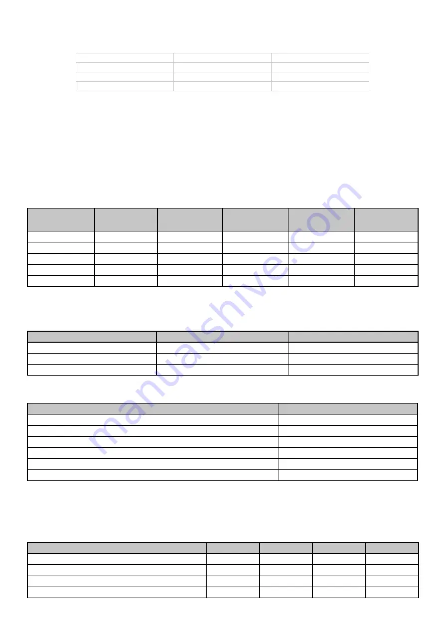
12.3.1 CORRECTIVE FACTORS
Percentage of glycol
Freezing point [°C]
Yeld corrector factor
Absorbed power
correction factor
Water flow
correction
factor
Pressure drop
correction
factor
10%
-3,2
0,985
1
1,02
1,08
20%
-7,8
0,98
0,99
1,05
1,12
30%
-14,1
0,97
0,98
1,10
1,22
40%
-22,3
0,965
0,97
1,14
1,25
50%
-33,8
0,955
0,965
1,2
1,33
12.3.2 CORRECTION FACTORS FOR USE OF WATER-GLYCOLE MIXTURE
The correction factors for water flow rate and pressure drop must be applied to the values obtained without the use of glycol. The correction
factor for water flow rate shall be calculated to maintain the same temperature difference as would be obtained without the use of glycol. The
pressure drop correction factor is applied to the water flow rate value corrected by the water flow rate correction factor.
m² °C/kW
Power output correction factor
Power input correction factor
0,44 x 10
-1
1,00
1,00
0,88 x 10
-1
-0,99
1,00
1,76 x 10
-1
0,98
1,00
12.3.3 SCALING CORRECTION FACTOR
The correction factors due to contamination of the internal gas/water exchanger are shown below.
Description
Value
Low pressure switch
46 bar
High pressure alarm
40 bar
Low pressure alarm
1,3 bat heating / 3,5 bar cooling
Maximum number of restarts/hour after high/low pressure (manual reset)
3
Antifreeze protection (standard version)
+3 °C
Hydronic circuit safety valve
6 bar
12.3.4 CALIBRATIONS AND PROTECTIONS CONTROL
Check that the antifreeze mixture concentration is suitable for the freezing temperature.
12.3.5 CORRECTION FACTORS DEPENDING ON ALTITUDE
Altitude [m]
500
1000
1500
2000
Correction factor heat output
0,9964
0,9941
0,9888
0,9869
Correction factor power input in heating mode
0,9931
0,9841
0,9853
0,9755
Correction factor cooling capacity
0,9888
0,9762
0,9618
0,9466
Correction factor power input in cooling mode
1,0106
1,0235
1,0386
1,0560
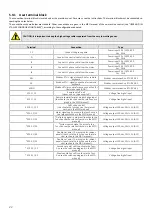
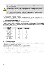
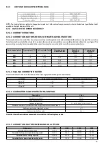
12.2
UNIT AND AUXILIARY ELECTRICAL DATA
Unit power supply
V/~/Hz
400/3PH+PE/50
On board controller circuit
V/~/Hz
12/1/50
Remote controller circuit
V/~/Hz
12/1/50
Fan power supply
V/~/Hz
400/3PH+PE/50
NOTE: The electrical data are subject to change due to updates. It is therefore always necessary to refer to the technical specifications label
applied on the right side panel of the unit.


