background image

25

ENGLISH

Installation Instructions

Commissioning must be done by profes-

sionally qualified personnel. Unical AG 

S.p.A. will not be held liable for damage 

to persons, animals or objects due to fail-

ure to comply with the above instruction. 

Before commissioning the boiler, check that:

3.10 - COMMISSIONING

does the installation meet the specific standards and  regulations in force, both relating to the

gas part as well as the electrical part?

do the combustion air intake and flue gas exhaust take place properly according to

what is defined by the specific rules and regulations in force?
is the fuel supply system sized according to the capacity required by the boiler? 

Is it equipped with all safety and control devices required by the standards in force?

is the power supply of the boiler 230V - 50Hz?

has the system been filled with water (approximately 0.8/1 bar pressure on the pressure gauge 

with the pump stopped)?

Has the condensation drain trap been filled with water as indicated in chapter 3.7?

are any system shut-off gate valves open?

does the gas to be used correspond to the boiler calibration gas?: otherwise, perform the boiler 

conversion in order to use the gas available (see section: 4.3”);

this operation must be carried out by technical staff qualified in compliance with the standards in force;
is the gas supply valve open?

has the system been checked for gas leaks?

is the outside main switch ON?

is the system safety valve efficient and is it connected to the drains?

is the condensation drain trap connected to the drains? 
has the system been checked for water leaks?

are the ventilation conditions and minimum distances to perform any maintenance

ensured?

have the GAS, HEATING and DOMESTIC HOT WATER pipes been cleaned thoroughly with 

products suitable for each circuit?

has a surveillance and protection system against gas leaks been installed? (Optional)

are the system pipes NOT used as the electrical system earthing? 

has the system been sized properly bearing in mind the radiator pressure drops? 

thermostatic valves, radiator stop valves 

has the operator been trained and has the documentation been supplied?

Please tick the operations performed

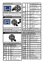
Switching boiler on and off

NOTE!

Further details in the section 

‘‘Technical Information’’ on the boiler 

page of the unicalag.ag website 

Summary of Contents for KONe C 18

Page 1: ...E N G L I S H INSTALLATION AND SERVICING MANUAL R 18 C 18 R 24 C 24 R 28 C 28 R 35 C 35 ...

Page 2: ... It can be taken to a special recycling centre managed by the local authorities or to a dealer who offers this service Separate disposal of a domestic appliance avoids possible negative consequences for the environment and human health deriving from inappropriate waste handling and allows the recovery of the materials of which it is made in order to obtain significant energy and resource savings ...

Page 3: ...ited from the control panel 33 4 3 Adaptation of the power to the heating system 37 4 3 1 GAC adjustment 38 4 4 Important notes 39 4 5 Wiring diagram 40 4 6 Error codes 41 3 INSTALLATION INSTRUCTIONS 15 3 1 General warnings 15 3 2 Installation standards 15 3 3 Preventive system verification and adjustment operations 15 3 4 Packaging 16 3 4 Positioning the boiler 17 3 6 Flue gas exhaust pipe connec...

Page 4: ...it was expressly designed Any other use is to be considered improper and therefore dangerous 1 1 general warnings The instruction booklet is an integral and essential part of the product and must be kept by the user Read the warnings contained in this instruction booklet carefully as they provide important guidelines regarding installation use and maintenance safety Keep the booklet with care for ...

Page 5: ...user as well as other documents concerning the appliance inserted in the envelope inside the packaging The user must keep this documentation safe for future consultation Inform the user about the importance of the air vents and the flue gas exhaust system high lighting their essential features and the absolute prohibition of modifying them Inform the user concerning controlling the system s water ...

Page 6: ...ch affect the operating safety of the appliance Attention To tighten or loosen the screwed fittings use only appropriate fixed spanners Incompliant use and or inappropriate tools can cause damage e g water or gas leakage ATTENTION Indications for propane gas fired appliances Make sure that the gas tank has been deaerated before installing the appliance For state of the art tank venting contact the...

Page 7: ... T max Max domestic hot water temperature C Electrical characteristics 21 Electrical power supply 22 Consumption 23 Protection rating D Countries of destination 24 Direct and indirect countries of destination 25 Gas category 26 Supply pressure E Factory settings 27 Adjusted for gas type X 28 Space for national brands G ErP 29 Seasonal space heating energy efficiency 30 Energy efficiency in DHW pro...

Page 8: ...rfac es must be clean see system protection ACCESSO RIES sect in domestic price list This protection can intervene only if the electricity and gas supplies are connected If one of the two is not available and upon reset 11 SR a temperature of 2 C is detected the appliance will behave as described in tab pos 2 The heating system can be protected effectively from frost by using antifreeze products w...

Page 9: ...ICATION OF THE MAIN COMPONENTS AND DIMENSIONS View from above View from below NOTE Further details in the section Technical Information on the boiler page of the www unicalag it website KONe 18 24 R KONe 18 24 C 22 13 23 24 11 4 25 10 1 2 3 15 26 17 20 16 12 18 5 27 21 22 13 23 24 11 4 25 10 3 26 15 20 12 18 5 27 21 ...

Page 10: ...10 View from above View from below KONe 28 35 R KONe 28 35 C 15 26 20 17 22 11 24 18 4 25 10 1 2 5 8 12 16 13 23 3 27 22 11 24 18 4 25 10 3 5 8 12 13 15 26 20 23 27 ...

Page 11: ...h 14 Boiler drain valve 15 Filling valve 16 Diverter valve 17 Plate heat exchanger 18 FL FH VM Fan 19 AF AS PV Flue gas pressure switch 20 Safety valve 21 Automatic by pass 22 rb SRR Return temperature sensor 23 tf TLC Flue gas collector safety ther mostat 24 Aluminium Heat Exchanger Ca pacitor 25 Vent valve 26 Condensation drain trap 27 SL Arrangement for condensate sensor level C Domestic hot wa...

Page 12: ... 2 3 DIAGRAM OF FLOW RATE PRESSURE AVAILABLE FOR INSTALLATION Flow rate l h Flow rate l h Avaible Head m c a metres of water Avaible Head m c a metres of water MODULATING PUMP DIAGRAM OF FLOW RATE PRESSURE AVAILABLE FOR INSTALLATION ...

Page 13: ...nominal kW 17 23 27 32 Seasonal space heating energy efficiency ƞs 93 92 93 93 Seasonal efficiency class in heating mode A A A A For CH only and combination boilers useful heat output Useful Heat Output in high tempera ture regime Tr 60 C Tm 80 C P4 kW 10 3 12 7 15 8 18 2 Useful efficiency at nom heat output in high temperature regime Tr 60 C Tm 80 C ƞ4 88 1 87 0 88 4 87 5 Useful heat output at 30...

Page 14: ... 5 0 5 Maximum domestic hot water circuit pressure bar 6 6 6 6 Domestic hot water specific flow rate t 30 C D l min 11 2 11 2 13 16 Production of D H W in continuous operation with t 45 K l min 7 4 7 4 8 6 10 1 Production of D H W in continuous operation with t 40 K l min 8 3 8 3 9 7 11 4 Production of D H W in continuous operation with t 35 K l min 9 5 9 5 11 1 13 0 Production of D H W in continu...

Page 15: ...is dust and or if there are aggressive corrosive vapours present in the installation room the appliance must be protected suitably and must be able to operate independently from the air in the room Attention Only mount the appliance on a closed wall made of non flammable materi al flat vertical so that the minimum distances required for installation and maintenance can be observed The boiler must ...

Page 16: ...r ob jects due to failure to comply with the instruction above H P L As well as the appliance the packaging contains A DOCUMENTATION ENVELOPE System booklet User operating instructions booklet Instruction booklet for the installer and maintenance engineer Warranty 2 Spare parts form Certificate of conformity B Connection predisposition paper template C Chimney spacer 2 1 3 4 PACKAGING P depth L wi...

Page 17: ...t its weight The wall must not be made of flammable material KONe Since the temperature of the wall on which the boil er is installed and the temperature of the coaxial exhaust pipe do not exceed in normal operating conditions a room temperature beyond 60 K it is not necessary to observe the minimum distances from flammable walls For boilers with double intake and exhaust pipes in the event of cro...

Page 18: ...Horizontal exhaust and intake terminals directed outside via coaxial or double pipes C33x C33 TOTAL LENGTH LA intake L Exhaust COAXIAL Ø60 100 DOUBLE Ø80 FROM m TO m FROM m TO m 1 7 0 5 0 5 40 20A 20S COAXIAL Ø80 125 DOUBLE Ø60 FROM m TO m FROM m TO m 1 9 1 1 20 10A 10S ertical exhaust and intake terminals directed out side via coaxial or double pipes C53x C53 C53 NOT ALLOWED C53 TOTAL LENGTH LA i...

Page 19: ...s in the MT018 available on the website ATTENTION For the type of connection B23P the room follows the same installation rules for boilers with natural draught Please note these values relate to exhausts made by means of rigid pipes and smooth original UNICAL C83x C83 Connection to a terminal for combustion air intake and flue gas exhaust via a single or collective chimney C93x C93 Air flue gas th...

Page 20: ...flue gas exhaust refer to the Technical Information section on the boiler page of the www unicalag it website It is recommended to only use original Unical exhaust pipes The supplier will have no contractual or extra contractual liability for damage caused due to incorrect installation and use and in any case failure to comply with the instructions provided by the manufacturer Concentric start Ada...

Page 21: ...1 2 Sc BOILER DRAIN S cond CONDENSATION DRAIN Rc FILLING VALVE Svs SAFETY VALVE DRAIN Provide a drain pipe with funnel and a trap that lead to a suitable drain in cor respondence of Svs This drainage must be controlled on sight If this precaution is not taken trigger ing of the safety valve can cause dam age to persons animals and objects for which the manufacturer cannot be held responsible Conde...

Page 22: ...This operation must be performed carefully respect ing the following phases open the radiator vent valves and make sure the automatic valve is working properly in the boiler open the filling tap gradually making sure that the automatic air release valves installed on the system work properly close the radiator air release valves as soon as water comes out check the pressure gauge until pressure re...

Page 23: ...inals TA1 OT after having removed the jumper ON OFF room thermostat connection RT OT A3 4 32 1 6 5 SE TA 1 OT TA 2 WH WH Y Y BK BK TA ON OFF Danger Only a qualified technician may per form the electrical installation Before performing connections or 3 9 ELECTRICAL CONNECTIONS any type of operation on electrical parts always disconnect electrical power and make sure that it cannot be reconnected ac...

Page 24: ...boiler installation requires electric al con nection to the mains power supply This connection must be made up to standard as required the regulations in force Remember that a bipolar switch must be nstalled on the boiler power line with over 3 mm between contacts easy to access making maintenance quick and safe The power cable must be replaced by technical personnel authorised by UNI CALAG S p A ...

Page 25: ...does the gas to be used correspond to the boiler calibration gas otherwise perform the boiler conversion in order to use the gas available see section 4 3 this operation must be carried out by technical staff qualified in compliance with the standards in force is the gas supply valve open has the system been checked for gas leaks is the outside main switch ON is the system safety valve efficient a...

Page 26: ...lternates between SP and the flow temper ature the boiler operates at maximum output Perform combustion analyses 4 DISABLING The calibration function stays active for 15 min utes To disable the CALIBRATION function before the time elapses press the key D for 5 seconds until SErvice disappears 3 MINIMUM OUTPUT Press the key C when the low flame symbol is fixed on the display and it alternates betwe...

Page 27: ...in steady state conditions see par 3 11 1 3 11 2 Positioning the probes 3 12 ADJUSTING THE BURNER KONe R 18 KONe C 18 Type of Gas Effective Ouput kW Heating Thermal kW Capacity Supply Press mbar Fan speed rpm Collector diaphragm Ø n holes CO2 levels Con sumption Con sumption Start up power IG min max min max min max Gas nat G20 2 9 17 4 3 0 18 20 9 2 9 2 0 32 m h 1 9 m h Gas nat G25 2 9 17 4 3 0 1...

Page 28: ...10 5 0 43 kg h 2 17 kg h A P G230 4 3 27 2 4 4 28 0 20 9 6 9 0 0 34 m h 2 18 m h 0 2 Acceptable range for G20 G25 0 2 R Acceptable range for G31 G230 If the CO2 value detected is beyond the recommended range check the integrity of the electrode If needed replace the electrode If the problem persists one can use the function described below Note for operation with Propane air A P follow the procedu...

Page 29: ...Start up output xx Minimum output 0 EDITING THE VALUE When the flame flashes correct the value with keys C or C VALUES FROM TO DEFAULT 3 3 0 corresponds to about 0 5 points of CO2 SELECTION Select the modulation point on which to perform the adjustment max output start up output min output with key B Press key S 3 2 DISABLING Press the keys B and B at the same time for at least 10 seconds SErvice ...

Page 30: ...TEM Act on parameter HP par 4 2 SE parameters list to achieve the value corresponding to the desired output The user is NOT authorised to activate the func tion described below E g KONe 24 to decrease the output of the boiler to 18 kW edit parameter HP about 70 E g KONe 35 to decrease the output of the boiler to 24 kW edit parameter HP about 68 E g KONe 28 to decrease the output of the boiler to 2...

Page 31: ...701 Relation between the temperature C and the nom resistance Ohm of the heating probe SR and of the domestic hot water probe SS Example At 25 C the nominal resistance is 10067 Ohm At 90 C the nominal resistance is 920 Ohm 4 1 INSPECTION AND MAINTENANCE INSTRUCTIONS To assure long term functioning of your appliance and to avoid altering its approved status only original Unical AG S p A spare parts...

Page 32: ...water pressure is below 0 4 bar Without request close the shut off valves of the heating circuit open the drain valve to make the water pressure decrease Be fore pressurising again check the pressure of the expansion vessel Expansion vessel 8 Does the vessel contain the right amount of air Check the pressure in expen sion vessel 1 bar when the boiler is empty Pressurise the boiler open the pump au...

Page 33: ...he heat ing sensor is faulty External temperature if there is no external probe or if it is faulty Domestic hot water temperature if there is no sensor or if it is faulty Return temperature if there is no auxiliary sensor or if it is faulty Differential t between flow and return Heating temperature calculated been room zone ON OFF and remote zone OT Instantaneous fan speed _ _ rpm x 100 Water pres...

Page 34: ... of the position 01 in which the error is stored DISPLAY Press the key B to display the sequence of faults between 01 12 EDIT VALUE RESET Press the key D for over 5 seconds to reset the whole errors log This operation must only be performed in the event one wants to delete the log completely for example if important updates are made it may therefore be useful to have a new chronological reference ...

Page 35: ...t 10 0 30 External probe on Regolafacile 0 20 C 30 10 C default 10 0 5 30 Night reduction 0 T A default 5 30 night reduction 0 1 Domestic hot water pre heat function 0 Not active default 1 Active 0 100 Maximum heating modula tion level default 100 20 45 Minimum heating set point level default 30 50 85 Maximum heating set point level default 85 25 45 Minimum domestic hot water set point level defau...

Page 36: ...imum fan speed 10 750 rpmx100 0 199 Maximum fan speed 10 5000 r pmx100 1 20 Heating control proportional 1 20 Heating control integrative 1 20 Heating control derivative 1 20 Domestic hot water control proportional 1 50 Domestic hot water control integrative 1 20 Domestic hot water control derivative 3 90 Ramp time CH Value 10 sec 0 1 Function antilegionella storage tank boiler DISPLAY Press the k...

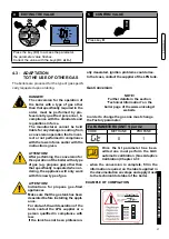
Page 37: ...tion of the tank contact the LPG supplier or a person qualified in compliance with law If the tank has not been profession 4 3 ADAPTATION TO THE USE OF OTHER GAS Gas Conversion The boilers are produced for the type of gas specifi cally requested upon ordering EDITING THE VALUE Press the key C to access the parameter the parameter value flashes Correct the value with the keys C or C 4 CONFIRM VALUE...

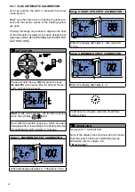
Page 38: ...s StArt scrolls on the display the function is active when the symbols flash Note After the ignition sequence which can also take place after a few attempts the boiler performs the calibration which consists of 3 stages Stage 1 MAXIMUM OUTPUT CALIBRATION When the display alternates tr 100 about 1 min Stage 2 START UP OUTPUT CALIBRATION When the display alternates tr with value XX 1 min Stage 3 MIN...

Page 39: ...y board MODULATION BOARD A universal board B memory board The memory board is programmed by de fault for METHANE gas operation In the event of LPG operation the GT pa rameter must be edited Factory parameters see Chap 4 2 In the event the memory board can be re used there is no need to reprogram parame ters settings and automatic calibration 4 4 IMPORTANT NOTES REPLACING COMPONENTS Before replacin...

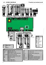
Page 40: ... 1 76 5 TLC TL SRR G G WH WH WH BL A6 VI WH R Mod On Off VG EV2 EV1 OR A3 4 32 1 6 5 SE BK TA 1 OT TA 2 WH WH Y Y BK BK MDV PK WSC YONOS GND WH SL BK CASING 4 5 WIRING DIAGRAM Practical connection board KEY A1 A9 Services connectors CMP Modulating pump control DK Water deficiency safety pressure switch E ACC RIL Ignition detection electrode FLS Domestic hot water request flow switch MVD Diverter v...

Page 41: ...ry sensor 22 45 2 WATER OVERPRESSURE detected if the H2 O pressure Transducer is present with pressure 2 5 bar it is reset automatically when H2 O pres sure 2 bar Wait for the values to return to default limits Replace the Transducer 30 3 SERVICE PARAMETERS Service parameters altered due to possible electromagnetic interferences Reset the altered parameters via the panel and or regola facile 21 4 ...

Page 42: ...of the sensor see table Res Temp Par 4 or its connections 12 15 HEATING SENSOR 11 Heating sensor fault Check the efficiency of the sensor see table Res Temp Par 4 or its connections 38 16 FACTORY PARAMETERS Alteration of the factory param eters due to possible electro magnetic interferences Press the unblock key if the anomaly persists replace the board 1 LIMIT THERM 17 SAFETY THERMOSTAT Intervent...

Page 43: ... circuit problems Gas Valve Check the Gas Valve connec tions Replace the Gas Valve 3 Replace the Modulation Board BLOCK 32 Gas Valve opening time beyond limit time Check the parts that generate the heat requests thermostats electrovalve limit switches flow switch etc BLOCK 33 Flame loss with max ignition value correction Check the gas pressure any flue gas recirculation in the chimney and obstruct...

Page 44: ...ight to bring those changes that it will hold necessary to it own products or profits without jeopardizing its essential characteristics 46033 casteldario mantova italia tel 39 0376 57001 fax 39 0376 660556 info unical ag com export unical ag com www unical eu AG S p A www unical eu ORIGINAL INSTRUCTION 00334659 b 1 a ed 03 18 ...

Reviews: