31
ENGLISH
Installation Instructions
KON
m
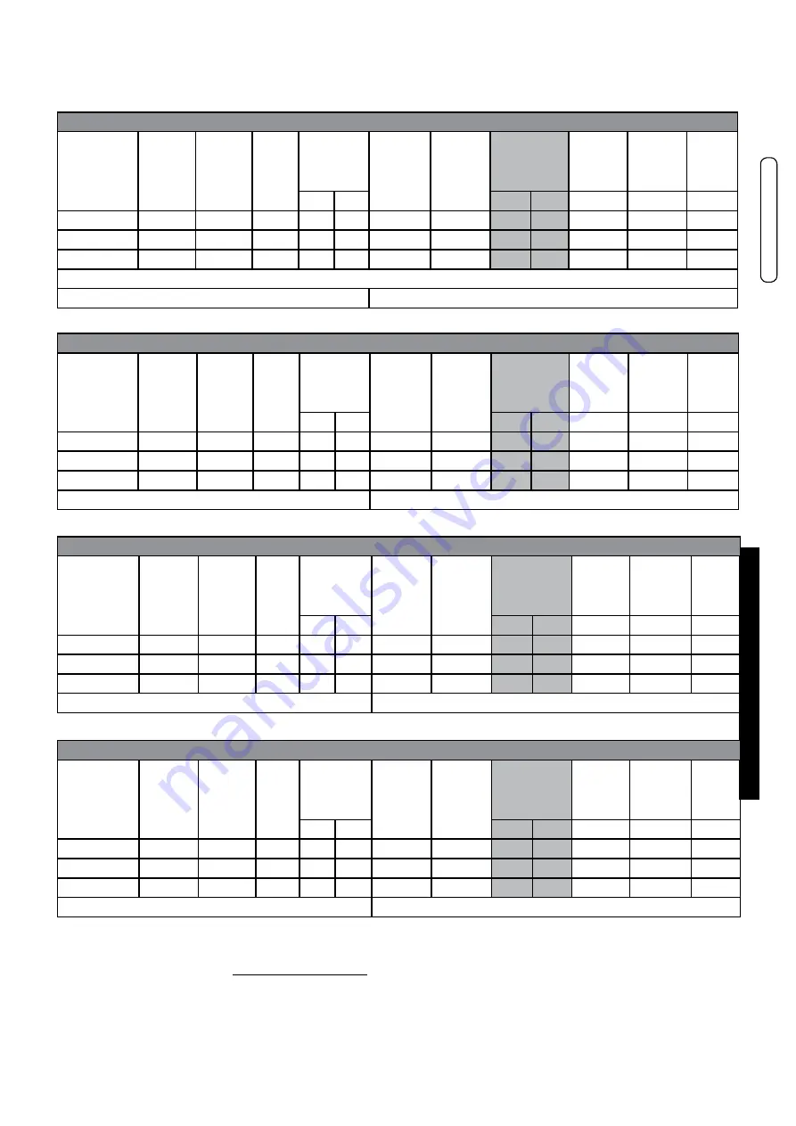
R 24 - KON
m
C 24
Type of
Gas
Effective
Output
[kW]
Heating
Thermal
[kW]
Capacity
Supply
Press.
[mbar]
Fan
speed
[rpm]
Collector
diaphragm
[Ø/n.
holes]
Diaphragm
VG
[Ø]
CO
2
levels
[%]
Con-
sump-
tion
Con-
sump-
tion
Start-up
power
IG
[%]
min max
min
max
min
max
Nat. gas (G20)
2,9 - 22,6 3,0 - 23,4
20
1400 7000
-
-
9,5
9,5
0,32 m³/h
2,47 m³/h
50
Nat. gas (G25)
2,9 - 22,6 3,0 - 23,4
25
1400 5700
-
-
9,5
9,5
0,37 m³/h
2,88 m³/h
50
Propane (G31)
4,2 - 22,6 4,4 - 23,4
37
1600 6600
-
-
11,2
11,2
0,34 kg/h
1,82 kg/h
35
(*) ± 0,2 Acceptable range for G20 / G25
(+) ± 0,2 Acceptable range for G31
KON
m
R 18 - KON
m
C 18 (#)
Type of
Gas
Effective
Output
[kW]
Heating
Thermal
[kW]
Capacity
Supply
Press.
[mbar]
Fan
speed
[rpm]
Collector
diaphragm
[Ø/n.
holes]
Diaphragm
VG
[Ø]
CO
2
levels
[%]
Con-
sump-
tion
Con-
sump-
tion
Start-up
power
IG
[%]
min max
min
max
min
max
Nat. gas (G20)
2,9 - 17,4 3,0 - 18,0
20
1400 5700
-
-
9,5
9,5
0,32 m³/h
1,90 m³/h
50
Nat. gas (G25)
2,9 - 17,4 3,0 - 18,0
25
1400 5700
-
-
9,5
9,5
0,37 m³/h
2,21 m³/h
50
Propane (G31)
4,2 - 17,4 4,4 - 18,0
37
1600 5300
-
-
11,2
11,2
0,34 kg/h
1,40 kg/h
35
(#) values in domestic hot water mode operation also for KON
m C 24
(*) ± 0,2 Acceptable range for G20 / G25
(+) ± 0,2 Acceptable range for G31
KON
m
R 28 - KON
m
C 28
Type of
Gas
Effective
Output
[kW]
Heating
Thermal
[kW]
Capacity
Supply
Press.
[mbar]
Fan
speed
[rpm]
Collector
diaphragm
[Ø/n.
holes]
Diaphragm
VG
[Ø]
CO
2
levels
[%]
Con-
sump-
tion
Con-
sumption
Start-up
power
IG
[%]
min max
min
max
min
max
Nat. gas (G20)
4,3 - 27,2
4,4 - 28,0
20
1200 6200
9,8x25 / 6
5,9
9.3
9.3
0.47 m³/h
2.96 m³/h
60
Nat. gas (G25)
4,3 - 27,2
4,4 - 28,0
25
1200 6200
9,8x25 / 6
6,5
9.3
9.3
0.54 m³/h
3.44 m³/h
60
Propane (G31)
5,4 - 27,2
5,6 - 28,0
37
1400 5900
9,8x25 / 6
4,7
10.5
10.5
0.43 kg/h
2.17 kg/h
60
(*) ± 0,2 Acceptable range for G20 / G25
(+) ± 0,2 Acceptable range for G31
KON
m
R 35 - KON
m
C 35
Type of
Gas
Effective
Output
[kW]
Heating
Thermal
[kW]
Capacity
Supply
Press.
[mbar]
Fan
speed
[rpm]
Collector
diaphragm
[Ø/n.
holes]
Diaphragm
VG
[Ø]
CO
2
levels
[%]
Con-
sump-
tion
Con-
sumption
Start-up
power
IG
[%]
min max
min
max
min
max
Nat. gas (G20)
4,3 - 32,0
4,4 - 33
20
1200 7000
9,8x25 / 6
5,9
9,3
9,3
0,47 m³/h
3,5 m³/h
50
Nat. gas (G25)
4,3 - 32,0
4,4 - 33
25
1200 7000
9,8x25 / 6
6,5
9,3
9,3
0.54 m³/h
4.06 m³/h
50
Propane (G31)
5,4 - 32,0
5,6 - 33
37
1400 6800
9,8x25 / 6
4,7
10,5
10,5
0,43 kg/h
2,56 kg/h
50
(*) ± 0,2 Acceptable range for G20 / G25
(+) ± 0,2 Acceptable range for G31
Check the levels of CO2 often, especially with low flow rates. They refer to the boiler with a closed
combustion chamber.
NOZZLES - PRESSURE - FLOw RATES TABLE
In some areas there may be particular distribution conditions of gas with a mixture that requires an opti
-
misation/adjustment of the appliance calibration
, compared to the calibration values made in the factory.

