27
2.6.4 - DHW STORAGE TANK
DHW production by an outer storage
tank connected to the boiler can be car-
ried out by an electric diverting valve or
a separated storage tank loading pump
Both devices can be chosen via the con-
trol panel push buttons, by selecting the
right parameter A (see paragraph
3.2.8.2, parameter A - 2
nd
digit).
The DHW tank NTC sensor, supplied
as an option, will be connected to the
terminals 7 – 8 of the 20-pole terminal-
strip.
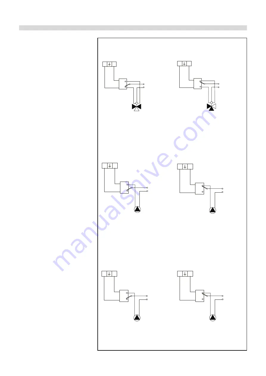
ELECTRICAL CONNECTION OF THE THREE WAY VALVE
WARNING!
There is a 230 V tension between terminals 16 - 18 only when there is a heat
demand by the DHW NTC sensor or by a DHW thermostat; in this case the display
will show :
4 XX (see 3.2.5).
Fig. 17
ELECTRICAL CONNECTION OF A DHW TANK
LOADING PUMP
ELECTRICAL CONNECTION OF A BOILER PUMP (OR A DHW LOADING
PUMP IF WITH A 3-WAY VALVE) Boiler pump or DHW loading pump
WARNING!
There is a 230 V tension between terminals 16 - 18 only when there is a heat
demand by the DHW NTC sensor or by a DHW thermostat; in this case the display
will show :
4 XX (see 3.2.5).
WARNING!
There is a 230 V tension between terminals 11 - 13 only when there is a heat
demand by the DHW NTC sensor or by a DHW thermostat; in this case the display
will show :
4 XX (see 3.2.5).
na
nc
c
16 17 18
B
DHW tank
Boiler AB
A Heating system
Line
3-contact relay
Neutral
L
N
V.D. Engine
Power
M
3-WAY VALVE CONNECTION
DHW tank
satisfied
na
nc
c
L
N
M
V.D. Engine
Power
Line
Neutral
B
DHW tank
Boiler AB
A Heating system
3-contact relay
3-WAY VALVE CONNECTION
DHW tank
not satisfied
16 17 18
na
nc
c
DHW tank loading pump
DHW
Tank satisfied
L
N
DHW tank
Pump Engine
Power
Line
Neutral
3-contact relay
16 17 18
na
nc
c
Line
Neutral
L
N
DHW tank
Pump Engine
Power
DHW tank loading pump
DHW
Tank not satisfied
3-contact relay
16 17 18
na
nc
c
11 12 13
CH loading pump/
DHW tank loading pump
L
N
Line
Neutral
3-contact relay
DHW tank
Pump Engine
Power
na
nc
c
11 12 13
L
N
Line
Neutral
CH loading pump/
DHW tank loading pump
3-contact relay
DHW tank
Pump Engine
Power


