28
The following diagrams are for reference only and therefore are not binding.
Unical declines any responsibility for errors or omissions.
3.12 - HYDRAULIC BASE DIAGRAMS
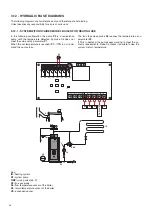
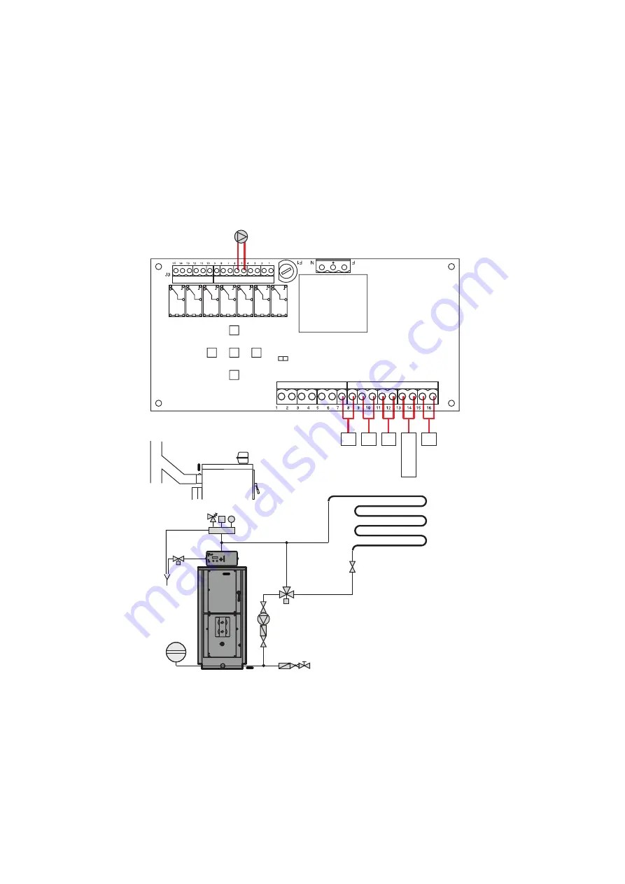
3.12.1 - SYSTEM WITH NOVAIREX MODEL BOILER FOR HEATING USE
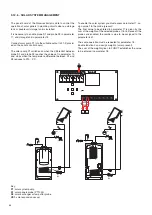
In the following configuration the pump
P2
is a recirculation
pump until the temperature detected by probe S4 does not
meet the value set by parameter
P1
.
When the set temperature is reached (
P1
), if
TA
is not in de-
mand the pump stops.
Key:
IR:
heating system
P2:
system pump
RMV:
mixing valve (55°C)
SF:
flue gas probe
S4:
flow temperature sensor of the boiler
S5
: return temperature sensor of the boiler
VE:
expansion vessel
VE
IR
RMV
P2
S5
S4
A
B
AB
S4
S5
SF
Micr
o por
ta
TA
P2
SF
Mors. 6 p. VERDE
Mors. 9 p. GRIGIO
J4
Morsett. 7 poli colore VERDE
Morsett. 9 poli colore GRIGIO
The fan stops when probe
S4
reaches the temperature set in
parameter
P0.
If TA is in demand, the pump keeps working, to meet the sy-
stem's requirements; Probe S5 makes it possible to view the
system's return temperature.
Door micros
witch
Summary of Contents for NOVAIREX 35
Page 1: ...INSTALLATION AND MAINTENANCE INSTRUCTIONS NOVAIREX 35 45 55 ...
Page 55: ......


