42
3.13.3 - GENERAL FEATURES AND
STANDARD EQUIPMENT
- Microprocessor circuit board with alphanumerical four line
LCD display, keyboard and indicator lights indicating activa-
tion of servomechanisms.
- EPROM non-volatile memory (in case of a power outage,
all previous settings remain valid). Stored data remain in the
memory for about 10 years without power.
- Wiring board for electrical connections.
- Basic probe supplied:
- 4 PTC probe with insulation ( 3 metre long)
- 1 PT1000 probe with insulation for solar system 3 metre long
- 1 PT1000 probe for measuring flue gas temperature 4 m
long
- Self-diagnosis program for incorrect installation or fault for
PTC temperature probes.
- 1 manual reset mechanical safety thermostat.
- Limit switch to be fitted on door opening mechanism (TKS).
OPERATING MODES:
Various operative modes may be controlled with the electronic
board:
1 HEATING ONLY
2 H PRODUCTION OF DOMESTIC HOT WATER
with single coil storage tank or
H PRODUCTION OF DOMESTIC HOT WATER
with double coil storage tank with control of supporting SO-
LAR PANEL SYSTEM.
2 H PRODUCTION OF DOMESTIC HOT WATER
with immersion storage tank (TANK in TANK) or HEATING
+ STORAGE TANK CONTROL (PUFFER) both with option
to have one coil and relevant supporting SOLAR PANEL
BACK-UP BOILER CONTROL
Before commissioning the boiler, you must choose the op-
erating mode and follow the instructions for configuration
of the board according to the type of system to be managed
(see diagrams below).
BOARD SUPPLY:
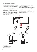
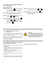
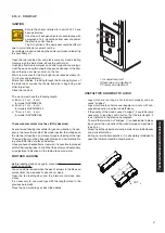
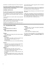
The circuit board has the following inputs:
- general 230 Vac power supply input
- probe S1 input to measure solar panel temperature (J1 1-2)
- probe S2 input to measure storage tank low point temperature
(solar exchanger) (J1 3-4)
- probe S3 input to measure storage tank high point temper-
ature (domestic hot water production) (J1 5-6)
- probe S4 input to measure BOILER FLOW temperature (J1
7-8)
- probe S5 input to measure BOILER RETURN temperature
(J1 9-10)
- FLUE GAS TEMPERATURE probe input (J1 11-12)
- wood loading door micro-switch contact input (TKS) (J1 13-
14)
- room thermostat or chronothermostat input for winter heating
system management (J1 15-16)
The board has the following outputs to control the servomech-
anisms:
- solar panel pump output (P1) (J3 1-2)
- storage tank pump output (P2) (J3 3-4)
- heating system pump output (P3) (J3 5-6)
- free output
- currently not powered (J3 7-8)
- fan output (for boilers without inverter)
- auxiliary boiler output (gas / oil) (J3 11-12)
- diverter valve output (J3 13-14-15)
Summary of Contents for NOVAIREX 35
Page 1: ...INSTALLATION AND MAINTENANCE INSTRUCTIONS NOVAIREX 35 45 55 ...
Page 55: ......

