29
Tec
hnical f
eatures and dimensions
ENGLISH
AttENtIoN!
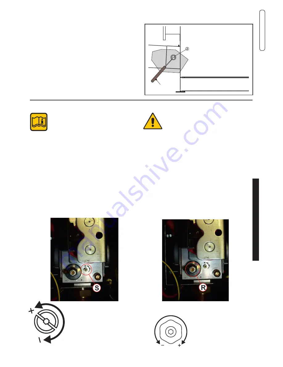
Remove cap 2,
Insert the co2
analysis probe
into the hole.
Air
drop
3.11.2 - POSITIONING THE PROBES
SPK 150
the following instructions are intended exclusively
for
authorised service personnel
.
3.12 - ADJUSTING THE BURNER
(S)
ADJUSTMENT SCREW
MAXIMUM OUTPUT
(R)
ADJUSTMENT SCREW
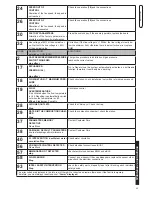
MINIMUM OUTPUT
- Remove the cap and insert the co2 analysis probe in the
flue gas sample point of the intake/exhaust terminal, see
chap. 3.11.2.
All boilers leave the factory already calibrated and
tested, however, in the event gas valve recalibration
is required (moduLE 1, moduLE 2)
To determine the combustion efficiency
one must make the following measurements:
- measurement of the combustion air temperature
- measurement of the flue gas temperature and content of
co
2
taken in the relevant hole 2.
take the measurements with the generator in steady state
conditions (see par. 3.11.1).
2) Minimum output adjustment
- operate the boiler in “calibration” mode at mINImum outPut
(see 3.11.1)
- once the burner is on, check that the “mINImum” co2 output
value corresponds to what is indicated in the table “NOZZLES
- PRESSuRE”.
- If necessary, adjust the value by turning (with a 2.5 mm hex
key) screw
“R”
cLocKWISE to increase it, ANtIcLocK-
WISE to decrease it
(see table NOZZLES-CAPACITY-PRESSURE).
1) Maximum output adjustment
- operate the boiler in “calibration” mode at mAXImum out-
Put (see 3.11.1)
- once the burner is on check
that the “mAXImum” co2 output value corresponds to that
indicated in the table “NOZZLES - PRESSURE”.
- If necessary, adjust the value by turning the
‘’S’’
adjustment
screw CLOCKWISE to decrease it and ANTICLOCKWISE
to increase it
(see table NOZZLES-CAPACITY-PRESSURE).


