23
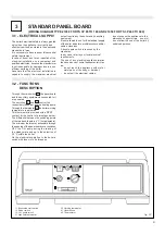
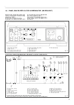
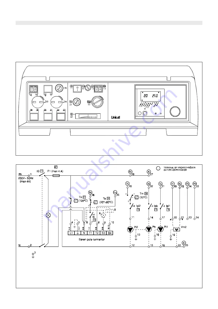
4.2 - PANEL BOARD WITH OUTER COMPENSATOR (ON REQUEST)
Note: The outer compensator arrives to the
customer with the technical data already
adjusted by UNICAL.
As far as the wiring and the using
instructions are concerned, please refer
fig. 25
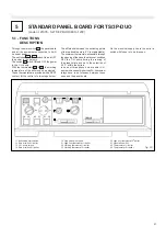
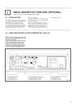
11 Illuminated main switch
12 Burner switch
13 C.H. pump switch for mixed zone
14 C.H. pump switch for direct zone
15 D.H.W tank loading pump switch
31 High limit thermostat
32 Working thermostat
41 General fuse (4A)
42 Boiler thermometer
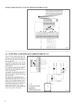
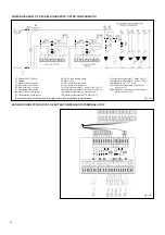
ELECTRICAL WIRING DIAGRAM PANEL BOARD WITH OUTER COMPENSATOR
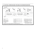
Ph Phase (230V ~ 50Hz)
N Neutral
F1 General fuse (max 4A)
Ib Burner switch
IG Illuminated main switch
Ipi1 1
st
C.H. pump switch
Ipi2 2
nd
C.H. pump switch
Ipb D.H.W. tank pump switch
Pb D.H.W. tank loading pump
Pi1 C.H. pump for direct zone
Pi2 C.H. pump for mixed zone
Te Working thermostat (30°C÷90°C)
Tm Minimum thermostat (30°C)
Ts High limit thermostat (100°C)
Vm2 Mixing valve for 2
nd
zone
A Burner lockout warning lamp (eventual)
B Hourmeter (eventual)
fig. 26
In case of three phase burner and/or pump, convenient relays have to be foreseen.
The outer compensator is not ready to accept the connection of an additional recirculating pump.
to the instruction manual supplied with
the outer compensator itself.
As far as the C.H. installation data are con-
cerned, please refer to the chapter 4.5 of
this manual.

