24
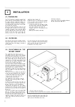
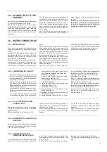
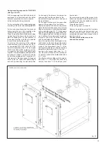
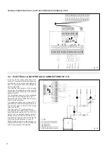
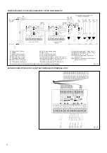
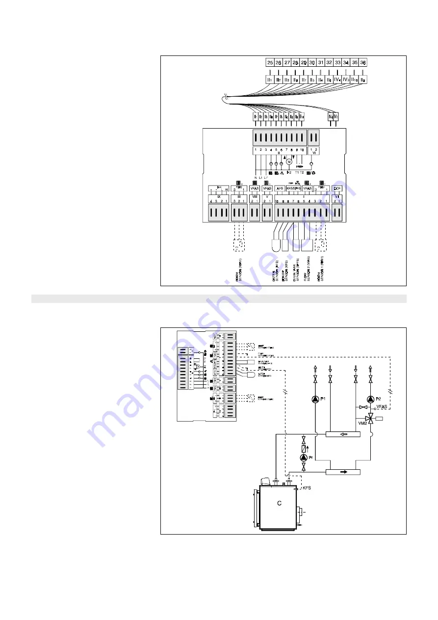
fig. 27
SENSOR CONNECTION ONTO THE OUTER COMPENSATOR TERMINAL STRIP
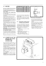
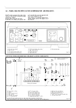
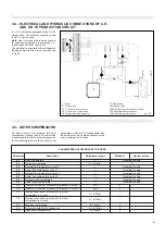
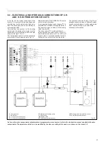
In the fig. 28 the typical connection of the
boiler to C.H. system with two heating zones,
of which one is with motorized mixing valve.
Both, the heating zones are controled by an
outer compensator.
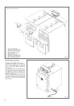
The electrical connections of the heating
pumps and the mixing valve motor must be
connected strictly according to the schema
shown in fig. 26.
The temperature sensors will be connected
according to the schema shown in fig. 27.
Remember that all the TRISECAL 3P boilers
are for forced circulation.
It is suggested to adopt a shunt pump "Pr" to
guarantee the circulation through the boiler in
any possible open condition of the mixing
valve (see fig. 28).
The shunt pump “Pr”, which will have a
throughput equal, at least, at 50% of the C.H.
pump and a manometric of of 1 m W.G., will
perform also an anticondensation function,
limiting the too cold returns into the boiler.
The hydraulic schemas shown in the figs. 28
& 29 are principle schemas; in case of
different system circuits, contact, please, our
after sale service dept., which will supply you
with all the necessary informations.
4.3 - ELECTRICAL AND HYDRAULIC CONNECTIONS OF C.H.
fig. 28
C Boiler
P1 C.H. pump for direct zone
P2 C.H. pump for mixed zone
Pr Shunt pump
VM2 Mixing valve
KFS Boiler temperature sensor
VFAS Flow temperature sensor

