Technical features and dimensions
7
2.1 - TECHNICAL FEATURES
The XC-K boilers are made up of an external shell which houses
the completely wet blind cylindrical furnace, where the first
two combustion gas passes are completed, and by a special
tube and shell, used for the third pass.
The tube and shell, placed horizontally in the lower part of the
body, is composed of stainless steel 316L tubes and aluminium
fins.
The guided path of the combustion gas exploits the thermal
exchange surfaces to a maximum and evenly balances strains
on the materials.
The construction fully complies with prescriptions laid down in
EN 303 part 1.
The components of the pressurised part, such as sheets and
tubes, are made in certified carbon steel, according to the
EURONORM 25 and EURONORM 28 tables.
Welding devices and procedures are approved by TÜV (D) -
UDT (PL) - SA (S) and ISPESL (I).
The boilers are equipped with an opening door on the right or left.
The outer shell is covered with a glass wool insulation 100 mm
thick, in turn protected by a mineral fibre fabric.
The top part of the shell is provided with hooks for lifting the
boiler.
Note: XC-K boilers are designed to operate with ON/OFF, dual
stage or modulating burner, as long as the minimum heat output
that can be reached is no lower than the value indicated on the
technical data plate.
The boilers are provided with two ½” attachments for conduits
with an inside diameter of 15 mm (suitable to house 3 bulbs
each).
The shell has holes at the sides for the cable glands of the
power, pumps, burner cables and those of any other auxiliary
device.
2
TECHNICAL FEATURES
AND DIMENSIONS
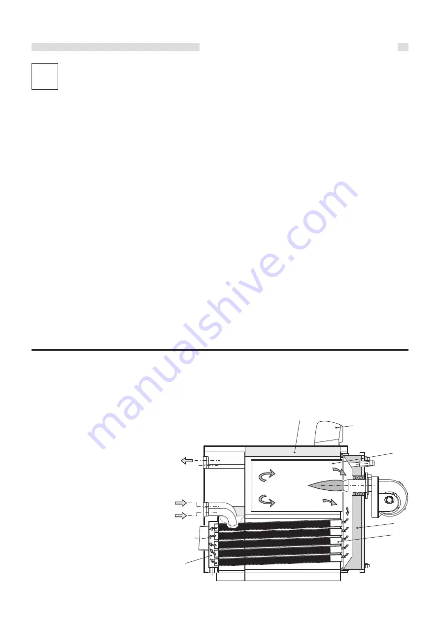
2.2 - MAIN COMPONENTS
XC-K boilers are equipped with a blind cylindrical furnace, in
which the central flame of the burner is reversed peripherally
towards the front. When the combustion gases have reached
the front part, they are sent through the door into the tubes of
the third pass to reach the rear flue gas chamber and then the
chimney.
The combustion chamber is always pressurised while the burner
is operating, within the power range of the boiler.
For the value of this pressure, see the tables
on pages 8÷10, in the column “Flue gas side
pressure drops”.
The chimney must be calculated so that
no positive pressure is detected
at its base.
1
Furnace
2
Smoke pipes with smoke diverters
3
Door with flame sight glass
4
Smoke chamber
5
Body insulation
6
Panel board
M Flow
Rbt Low temperature return
Rat High temperature return
fig. 1
1
2
3
6
5
4
M
Rat
Rbt


