Electrical Installation 4-63
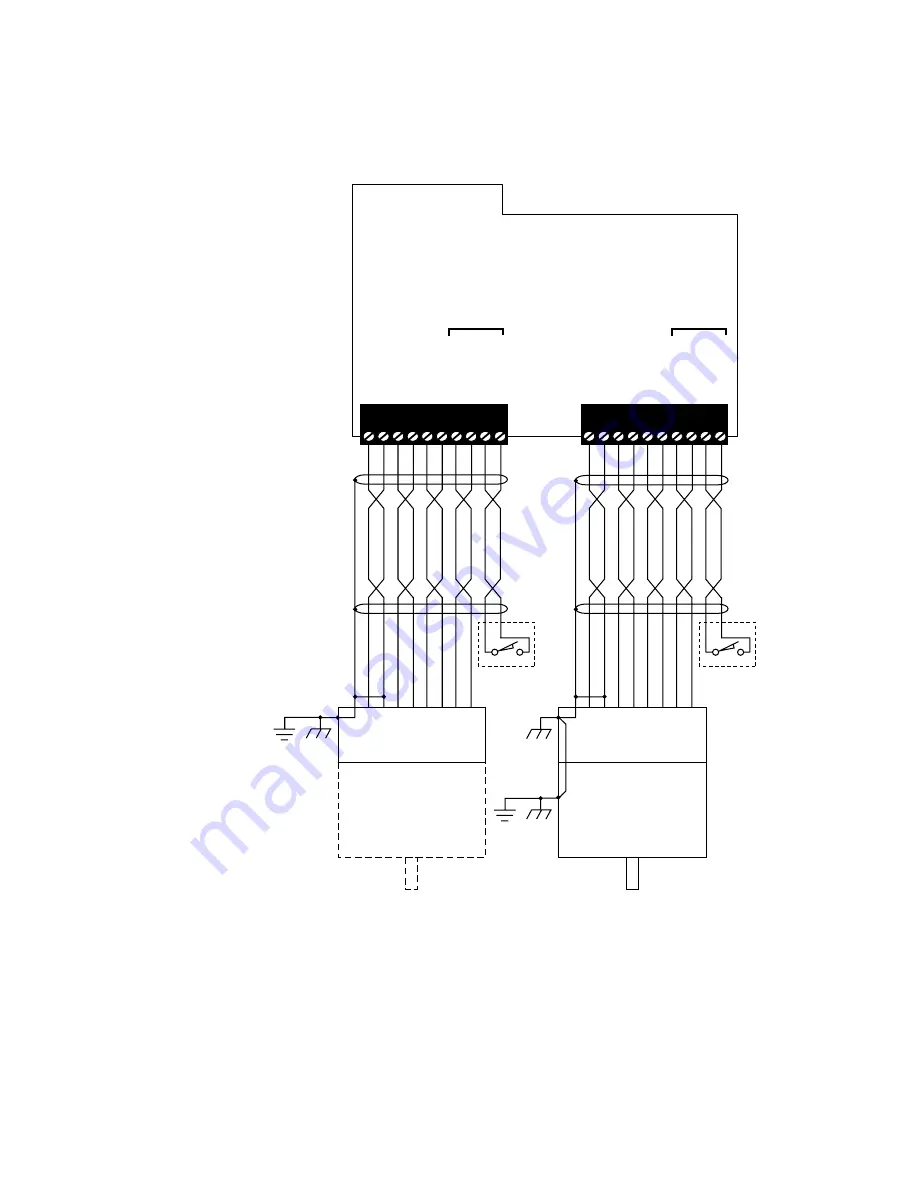
Figure 4-19—Dual Encoder Interface Module Connections
(321-952)
Marker should
occur once
per revolution
Encoder
Tie encoder case
to earth ground
isolated Common
Tie shield to
and to encoder case
open this end
Leave shield
Marker should
occur once
per revolution
Encoder
Motor
PE
PE
Motor case must
be earth grounded
Tie encoder case
to motor case
isolated Common
Tie shield to
Optional
Optional
and to encoder case
open this end
Leave shield
1 2 3 4 5 6 7 8 9 10
CON3
Load Feedback
Socket
Motor Feedback
Socket
CON2
IS5 V DC
ISOLATED COM
PGA1 +
PGA1 –
PGB1 +
PGB1 –
M
MARKER1 –
IS5 V DC
ISOLATED COM
PGA0 +
PGA0 –
PGB0 +
PGB0 –
M
MARKER0 –
REFE
REFERENCE0 –
1 2 3 4 5 6 7 8 9 10
REFE
REFERENCE1 –
Optional
Optional
Summary of Contents for 11100
Page 40: ...2 30 1000 Series Guide to Installation Troubleshooting and Maintenance...
Page 163: ......
Page 164: ......


