Electrical Installation 4-19
transducer, you may have to rephase it during start-up. Refer to the application
documentation for further information.
High-frequency voltage switching on these connections necessitates care to minimize
electrical noise interference. Make certain that motor outputs are routed separately from
control signals and AC input power and that control signals are appropriately shielded.
4.7
Connect the Dynamic Braking Resistor
Dynamic braking control for use with an external resistor is included on Form 12N and
17N 1105 drives, on all 1120 drives, and on Form 9N and 13N 1200 drives. It is
optionally available on other 1105 drives, on Form 17X and 34X 1200 drives, and on all
1100 and 1110 drives. Drives with optional braking control have terminals labeled B+
and DB. Units having only B+ and B– with no DB terminal do not feature dynamic
braking.
Connect the braking resistor to the B+ and DB terminals using the appropriate connection
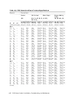
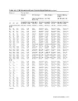
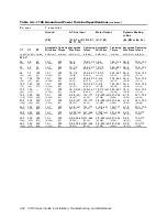
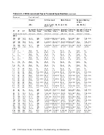
diagram as listed in Table 4-1. Dynamic braking terminal specifications for the various
drives are provided in the tables summarized in Table 4-1. Refer to Section 4.2 for wiring
requirements.
Dynamic braking resistors are available from the factory or you may supply your own.
Resistors are sized to give a braking torque of either 100% of rated constant torque with
integral control or 100%, 150%, or 200% of rated constant torque with optional control.
Resistors with a capacity of 5%, 10%, or 20% of the associated drive constant-torque
power rating. Consult the factory for other combinations. If providing your own resistor,
size it according to Table 4-17, which lists recommended values for providing a braking
torque of 100% of rated constant torque with integral braking control and 150% with
optional braking control. Make certain braking resistors provide at least the minimum
resistance specified in Table 4-18 to accommodate braking device current limitations.
Consult the factory for sizing assistance.
!
Attention
The braking resistor should be mounted in a well-ventilated area. Avoid
placing it in a location where heat could cause injury or property damage.
The resistor should be housed in a metal enclosure to shield neighboring
equipment from electromagnetic emissions. If it is mounted outside of the
enclosure, a guard should be constructed to prevent accidental contact.
!
Attention
Do not connect any kind of power supply to the dynamic braking resistor
terminals. Do not connect a resistor rated less than specified.
Summary of Contents for 11100
Page 40: ...2 30 1000 Series Guide to Installation Troubleshooting and Maintenance...
Page 163: ......
Page 164: ......


