Electronic System
- 32 -
Connector
(4508A)
CZ1
CZ2
CZ
3
CZ4
CZ
5
CZ6
CZ7
J3
J8
J1
7
J1
8
CN
1
CN
2
PCB
(SST8.412.113)
CZ1
CZ2
CZ
3
CZ4
CZ
5
CZ6
CZ7
J3
J8
J1
7
J1
8
CN
1
CN
2
L
N
Power Supply Socket
(3EGG1-2)
L
N
1
4
2
5
Power Switch
(R220-22C-11D)
1
4
2
5
3
2
1
4
5
6
115V/230 Selector
(L21-22A1)
3
2
1
4
5
6
Red
Blk
Red
Blk
L
N
(-12V) -V
(+12V) +V
COM
+5V
Switch Power
(T-60B)
L
N
(-12V) -V
(+12V) +V
COM
+5V
J4
J2
J3
J1
PCB
(SST8.411.130A)
J4
J2
J3
J1
Red
Wht
Red
Wht
Red
Blk
Wht
Org
Transformor
Brw
Org
J2
J3
J4
J5
J1
J6
J7
J8
J1
0
J1
1
J9
PCB
(SST8.411.128A)
J2
J3
J4
J5
J1
J6
J7
J8
J1
0
J1
1
J9
Pu
r,
R
e
d
Bl
u
,Bl
k
Yel
,Or
g
Gr
y
,W
h
t
Co
o
li
n
g
F
a
n
R
e
c
tif
ie
r
Tra
n
s
is
to
r1
T
u
ngs
te
n L
a
m
p
D
e
u
te
ri
u
m L
a
mp
Tra
n
s
is
to
r2
GND
Yel/Grn
Yel/Grn
Yel/Grn
Wht,Brw,Org,Red
J1
J2
PCB
(SST8.413.104A)
J1
J2
J1
J3
PCB
(SST8.412.314A)
J1
J3
J3
CZ4
CZ6
CZ
4
1
CZ
6
1
J3
1
PCB
(SST8.417.100)
J3
CZ4
CZ6
CZ
4
1
CZ
6
1
J3
1
A
u
to
-cel
l C
o
n
n
ec
to
r
Pr
o
g
ra
m
Sw
it
c
h
LC
D
C
o
n
tra
s
t
A
d
ju
st
e
r
Pr
in
te
r P
o
rt
RS
-2
3
2
CN1
CN2
J4
J5
J6
J9
J1
2
J1
4
PCB
(SST8.414.104)
CN1
CN2
J4
J5
J6
J9
J1
2
J1
4
CN1
LCD
CN1
Keypad
L
ig
h
t C
h
a
n
g
e
M
o
to
r
Fi
lt
er
M
o
te
r
W
av
e
le
n
g
th
M
o
to
r
F
il
te
r P
h
ot
o-
c
o
u
p
le
r(
P
C
B
:S
S
T
8
.4
17.
101
)
L
ig
h
t
C
h
a
n
g
e
L
im
it S
w
itc
h
Fu
s
e
5H
2
5
0V
,3
.1
5A
Ye
l/
G
rn
Ye
l,
Gr
n
W
ave
le
ng
th
P
h
o
to-
co
u
p
le
r(
P
C
B
:S
S
T
8
.4
1
5
.0
01
-D
)
Only for UV-2802
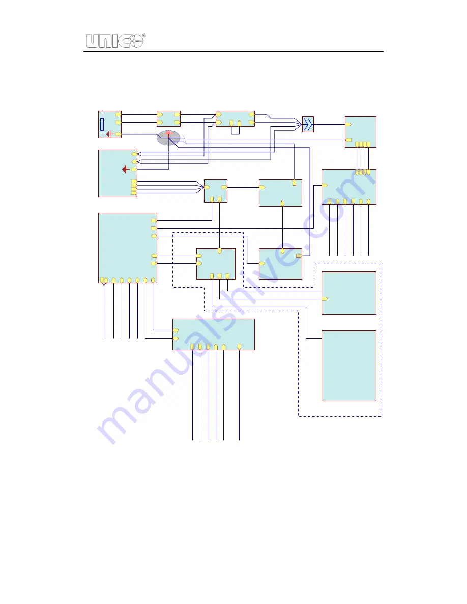
Figure 5.2 Connection of UV-2802, UV-2802PC
Summary of Contents for SQ Series
Page 5: ......
Page 8: ...Introduction 3 Figure 1 5 Model UV 4802...
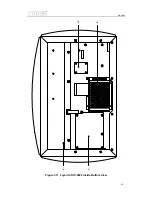
Page 12: ...Layout 7 Figure 3 2 Layout of UV 2800 Inside Bottom View...
Page 13: ...Layout 8 39 40 41 42 43 Figure 3 3 Layout of UV 2800 Top View...
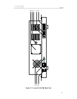
Page 14: ...Layout 9 230V 44 45 46 47 48 49 50 51 Figure 3 4 Layout of UV 2800 Back View...
Page 18: ...Layout 13 Figure 3 7 Layout of UV 2802 S UV 2802PC S Inside Bottom View...
Page 19: ...Layout 14 43 44 45 46 47 Figure 3 8 Layout of UV 2802 S Top View...
Page 20: ...Layout 15 230V Figure 3 9 Layout of UV 2802 S UV 2802PC S Back View...
Page 23: ...Layout 18 Figure 3 11 Layout of UV 3802 Inside Bottom View...
Page 24: ...Layout 19 44 45 46 47 48 Figure 3 12 Layout of UV 3802 Top View...
Page 25: ...Layout 20 230V Figure 3 13 Layout of UV 3802 Back View...
Page 28: ...Layout 23 Figure 3 14 Layout of UV 4802 Inside Top View...
Page 29: ...Layout 24 Figure 3 15 Layout of UV 4802 Inside Bottom View...
Page 30: ...Layout 25 43 44 45 46 47 Figure 3 16 Layout of UV 4802 Top View...
Page 31: ...Layout 26 230V Figure 3 17 Layout of UV 4802 Back View...
Page 35: ...Optical 30 Figure 4 3 Optical System schematic diagram of UV 4802...
Page 49: ...Electronic System 44 Figure 5 13 Layout of Main CPU PCB...
Page 63: ...Trouble Shooting 58 6 Trouble Shooting 6 1 Tungsten lamp off...
Page 69: ...Trouble Shooting 64 6 8 Slit check failed Only for UV 2802S UV 2802PCS...
Page 72: ...Trouble Shooting 67 6 13 Get dark current for a long time...
Page 74: ...Trouble Shooting 69 6 15 Backlight OK but display nothing on LCD Display...
Page 77: ...Trouble Shooting 72 6 18 No DC 12V on PCB SST8 412 113...


