
©UNICOM 2004. UNICOM is a trademark of UNICOM Electric, Inc.
All Rights Reserved.
UNICOM Electric, Inc.
908 Canada Court
City of Industry, California 91748
U.S.A.
www.unicomlink.com
E-mail: info@unicomlink.com
Technical Support: 1.800.346.6668
International: 626-964-7873
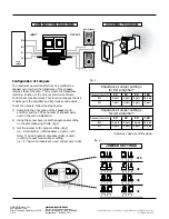
Impedance Jumper settings
for 4
Ω
amplifier*
Speaker Ohms (
Ω
)
2X
4X
8X
16X
8
Ω
4 pair
8 pair
16 pair
32 pair
4
Ω
2 pair
4 pair
8 pair
16 pair
*Assumes Volume set at Maximum
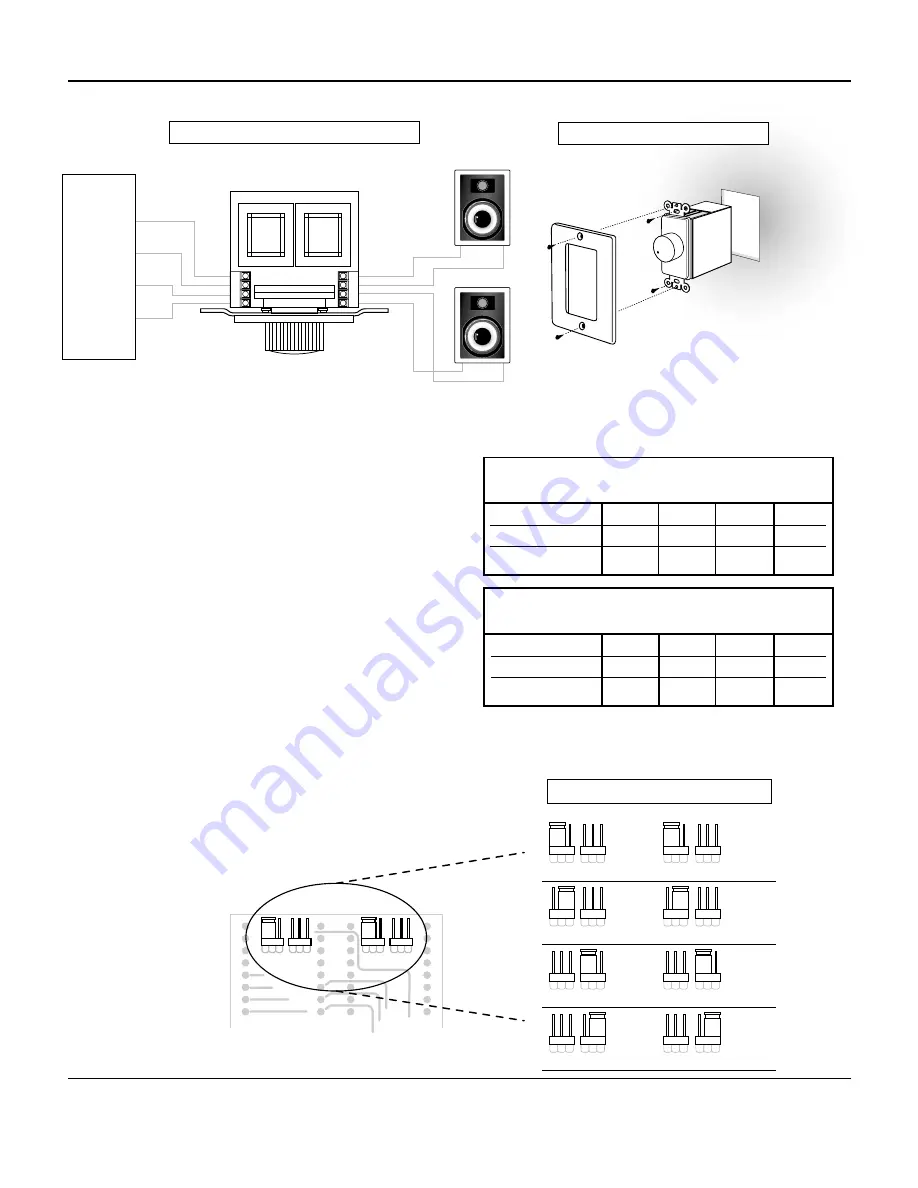
ASSEMBLY DIAGRAM
Impedance Jumper settings
for 8
Ω
amplifier*
Speaker Ohms (
Ω
)
2X
4X
8X
16X
8
Ω
2 pair
4 pair
8 pair
16 pair
4
Ω
1 pair
2 pair
4 pair
8 pair
CONNECTION DIAGRAM
INPUT
OUTPUT
RIGHT SPEAKER
LEFT SPEAKER
R+ R-
L-
L+
INPUT
L- L+
R+
R-
OUTPUT
R+
R-
L-
L+
AUDIO
SOURCE
Configuration of Jumpers
The maximum power transfer from an amplifier to a
speaker occurs when the impedance of the speaker
matches that of the amp. This is where the Impedence
matching function of the Unicom Full House Volume
Control becomes important. This function reduces the risk
of damage to the amplifier and improves sound quality.
To set the jumpers, follow the steps below.
1)
Determine the ohm rating of the speakers and
amplifier and the TOTAL number of speaker pairs
used in the entire installation.
2)
Using these numbers, locate the appropriate setting
on the accompanying charts. (fig.1)
3)
Set the jumper to the proper setting. (fig.2)
(i.e., 8
Ω
Amp 8
Ω
Sp 4 pairs = 4X)
Note: If an odd number of speaker pairs is used,
round up to next higher jumper setting.
(i.e., if 7 pairs of speakers are used, set jumpers to 8X)
X2
X4
X8
X16
X2
X4
X8
X16
X2
X4
X8
X16
X2
X4
X8
X16
X2
X4
X8
X16
X2
X4
X8
X16
X2
X4
X8
X16
X2
X4
X8
X16
JUMPER SETTINGS
X16
X8
X4
X2
fig. 1
fig. 2
X2
X4
X8
X16
X2
X4
X8
X16


