background image


Regulatory notes and statements 

Wireless LAN, Health and Authorization for use 

Radio frequency electromagnetic energy is emitted from Wireless LAN devices. The energy levels of 
these emissions however are far much less than the electromagnetic energy emissions from wireless 
devices like for example mobile phones. Wireless LAN devices are safe for use frequency safety 
standards and recommendations. The use of Wireless LAN devices may be restricted in some 
situations or environments, for example: 
·On board of airplanes, or 
·In an explosive environment, or 
·In case the interference risk to other devices or services is perceived or identified as harmful 
In case the policy regarding the use of Wireless LAN devices in specific organizations or 
environments (e.g. airports, hospitals, chemical/oil/gas industrial plants, private buildings etc.) is not 
clear, please ask for authorization to use these devices before operating the equipment. 

Regulatory Information/disclaimers 

Installation and use of this Wireless LAN device must be in strict accordance with the instructions 
included in the user documentation provided with the product. Any changes or modifications made to 
this device not expressly approved by the manufacturer may void the user’s authority to operate the 
equipment. The Manufacturer is not responsible for any radio or television interference caused by 
unauthorized modification of this device, of the substitution or attachment. Manufacturer and its 
authorized resellers or distributors will assume no liability for any damage or violation of government 
regulations arising from failing to comply with these guidelines. 

USA-FCC (Federal Communications Commission) statement 

This device complies with Part 15 of FCC Rules. Operation is subject to the following two 
conditions: 
1. This device may not cause interference, and 
2. This device must accept any interference, including interference that may cause undesired 

operation of this device. 

FCC Radio Frequency Exposure statement 

This Wireless LAN radio device has been evaluated under FCC Bulletin OET 65 and found 
compliant to the requirements as set forth in CFR 47 Sections 2.1091, 2.1093, and 15.247 (b) (4) 
addressing RF Exposure from radio frequency devices. The radiated output power of this Wireless 
LAN device is far below the FCC radio frequency exposure limits. Nevertheless, this device shall be 
used in such a manner that the potential for human contact during normal operation is minimized. 
When nearby persons has to be kept to ensure RF exposure compliance, in order to comply with RF 
exposure limits established in the ANSI C95.1 standards, the distance between the antennas and the 
user should not be less than 20 cm. 

FCC Interference Statement 

This equipment has been tested and found to comply with the limits for a Class B digital device, 
pursuant to Part 15 of the FCC Rules. These limits are designed to provide reasonable protection 
against harmful interference in a residential installation. 
This equipment generates, uses, and can radiate radio frequency energy. If not installed and used in 
accordance with the instructions, it may cause harmful interference to radio communications. 
However, there is no guarantee that interference will not occur in a particular installation. If this 
equipment does cause harmful interference to radio or television reception, which can be determined 
by turning the equipment off and on, the user is encouraged to try and correct the interference by one 
or more of the following measures: 
1. Reorient or relocate the receiving antenna. 
2. Increase the distance between the equipment and the receiver. 

Summary of Contents for WEP-72104G-1

Page 1: ......

Page 2: ......

Page 3: ...plies with Part 15 of FCC Rules Operation is subject to the following two conditions 1 This device may not cause interference and 2 This device must accept any interference including interference that...

Page 4: ...rom all persons and must not be co located or operating in conjunction with any other antenna or transmitter CE Mark Warning This is a Class B product In a domestic environment this product may cause...

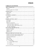
Page 5: ...ions 6 Connect the Router using LAN 6 Connect the Router using Wireless LAN 7 Check the installation 7 PC NETWORK TCP IP SETTING 8 Windows 95 98 ME 8 Windows 2000 9 Windows XP 10 WIRELESS ROUTER CONFI...

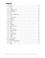
Page 6: ...g Setting 28 2 3 4 Statistic 29 2 3 5 Wireless 30 2 4 Routing 31 2 4 1 Static 31 2 4 2 Dynamic 31 2 4 3 Routing Table 32 2 5 Access 33 2 5 1 MAC Filters 33 2 5 2 Protocol Filter 33 2 5 3 IP Filter 34...

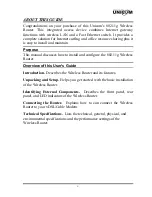
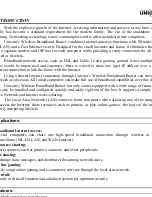
Page 7: ...configure the 802 11g Wireless Router Overview of this User s Guide Introduction Describes the Wireless Router and its features Unpacking and Setup Helps you get started with the basic installation of...

Page 8: ......

Page 9: ...1...

Page 10: ......

Page 11: ...s Wireless Broadband Router can solve twork access costs All linked computers can make full use of broadband capabilities over this de Unicom s Wireless Broadband Router not only comes equipped with...

Page 12: ...asy configuration via WEB Browser...

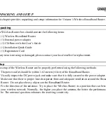
Page 13: ...can be properly performed using the following methods The power outlet should be within 1 82 meters 6 feet of the Broadband Router Visually inspect the DC power jack and make sure that it is fully se...

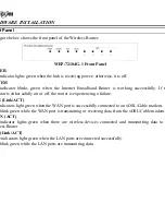
Page 14: ...r solidly on or off the router is experiencing a failure N Link ACT ndicators light green when the WAN port is successfully connected to an xDSL Cable modem blink green while the WAN port is transmitt...

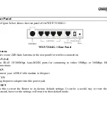
Page 15: ...ection AN 1 4 ur RJ 45 10 100Mbps Auto MDIX ports for connecting to either 10Mbps or 100Mbps Eth nnections AN nnect your xDSL Cable modem to this port C IN ug the power adapter into this power jack ES...

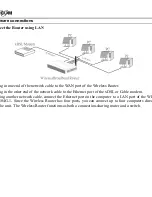
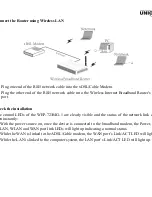
Page 16: ...the network cable to the Ethernet port of the xDSL or Cable modem ing another network cable connect the Ethernet port on the computer to a LAN port of the WE 104G 1 Since the Wireless Router has four...

Page 17: ...LEDs of the WEP 72104G 1 are clearly visible and the status of the network link c en instantly With the power source on once the device is connected to the broadband modem the Power LAN WLAN and WAN...

Page 18: ...95 98 ME NT 2000 XP is as follows dows 95 98 ME ick on the Network neighborhood icon found on the desktop ick the right mouse button and a context menu will be show lect Properties to enter the TCP IP...

Page 19: ...dialup connection applet Double click o ocal area network connection icon Select Properties to enter the TCP IP setting window In the Local area network status window click on Properties In the Local...

Page 20: ...cursor and click the right button on the My Network Place icon t properties to enter the TCP IP setting window et IP address to Obtain an IP address automatically et DNS to Obtain DNS server address a...

Page 21: ...s configured through an Eth nnection the host computer must be set on an IP subnetwork that can be accessed b DSL Cable modem For example when the default network address of the xDSL Cable m hernet in...

Page 22: ......

Page 23: ...he drop down list Please click Next to continue ep 3 Set LAN connection and DHCP server t user s IP address and mask The default IP is 192 168 1 1 To enable DHCP please click Enab HCP enable automatic...

Page 24: ...nection Obtain IP automatically Fixed IP addre E to obtain IP automatically PPPoE with a fixed IP address or PPTP n IP automatically DHCP client er has enabled DHCP server choose Obtain IP automatical...

Page 25: ...the Internet Service Providers assigned a fixed IP address choose this option and enter the ad bnet mask gateway IP and DNS IP addresses for your Broadband Router...

Page 26: ...obtain IP automatically nnected to the Internet using a PPPoE Dial up xDSL Modem the ISP will provide a Passwo User Name and then the ISP uses PPPoE Choose this option and enter the required informat...

Page 27: ...oE with a fixed IP address connected to the Internet using a PPPoE Dial up xDSL Modem the ISP will provide a Passwor er Name and a Fixed IP Address choose this option and enter the required informatio...

Page 28: ...ing an PPTP xDSL Modem enter the IP Address Subnet Ma way Server IP PPTP Account and PPTP Password in the appropriate fields If your ISP h ded you with a Connection ID enter it in the Connection ID fi...

Page 29: ...tions channel The SSID and channel must be the same as wireless de empting communication with the router ep 6 Restart e Setup wizard is now completed The new settings will be effective after the Wirel...

Page 30: ...host name is required by some ISPs The defa name is AP Router dress This is the IP address of the router The default IP address is 192 168 1 1 et Mask Type the subnet mask for the router in the text...

Page 31: ...the text boxes User s ISP will provide with this information NS 1 2 3 Type up to three DNS numbers in the text boxes User s ISP will provide with ormation AC Address If required by user s ISP type the...

Page 32: ...es users to set the time and date for the router s real time clock select properly tim and enable or disable daylight saving Time Displays the local time and date Zone Select the time zone from the dr...

Page 33: ...tions able Disable Enables and disables wireless LAN via the router ID Type an SSID in the text box The SSID of any wireless device must match the SSID typed order for the wireless device to access th...

Page 34: ...tion Type The authentication type default is set to open system There are three optio System Shared Key WPA and WPA PKS Enable or Disabled This is to make WEP enabled or disabled Select the key mode i...

Page 35: ...ver Enter the IP address of and the Port used by the Primary Radius Server Enter the Shared Secret which is used by the Radius Server Enter the IP address of Port and Shared Secret used by the Seconda...

Page 36: ...et transfer rates are minimized NOT is fragmentation threshold value may diminish system performance M Interval Type a DTIM Delivery Traffic Indication Message interval in the text box User c fy a val...

Page 37: ...NS ick DHCP Release to release all IP addresses assigned to client stations connected to the WA e router Click DHCP Renew to reassign IP addresses to client stations connected to the WAN 2 Log is scre...

Page 38: ...er wants the router to listen and recei ming Syslog messages Type Enables user to select what items will be included in the log System Activity Displays information related to router operation Debug I...

Page 39: ...4 Statistic is screen displays a table that shows the rate of packet transmission via the router LAN and W rts in bytes per second ick Reset to erase all statistics and begin logging statistics again...

Page 40: ...view information about wireless devices that are connected to the wirele r ected Time Displays how long the wireless device has been connected to the LAN via the router Address Displays the devices wi...

Page 41: ...with this information twork Mask Type the network subnet mask for user s network If user does not type a value e network mask defaults to 255 255 255 255 User s ISP or network administrator provides...

Page 42: ...mit parameters disabled RIP 1 or RIP 2 ve Click the radio buttons to set the desired transmit parameters disabled RIP 1 or RIP 2 Routing Table screen enables user to view the routing table for the rou...

Page 43: ...ternet access except those users in the MAC Table are denied In cess AC Table Use this section to create a user profile which Internet access is denied or allowed er profiles are listed in the table a...

Page 44: ...dress range filter no IP addres g within the range are allowed Internet access The IP filter profiles are listed in the table at t m of the page Note Click anywhere in the item Once the line is select...

Page 45: ...he item The line is sele d the fields automatically load the item s parameters which user can edit able Click to enable or disable the virtual server me Type a descriptive name for the virtual server...

Page 46: ...rt Range Type the port range that can be used to access the application in the text boxes Incoming Defines which incoming communications users are permitted to receive Protocol Selects the protocol TC...

Page 47: ...st with unlimited Internet access ply Click to save the settings 7 Firewall Rule is screen enables user to set up the firewall The router provides basic firewall functions by filt the packets that ent...

Page 48: ...where rule is applied Protocol Select the protocol TCP UDP or ICMP of the destination Port Range Select the port range Click to add the rule profile to the table at the bottom of the screen ate Click...

Page 49: ...hat pro mpatibility among networking equipment software and peripherals The Router is an UPnP en uter and will only work with other UPnP devices software If user does not want to use the U nctionality...

Page 50: ......

Page 51: ...up wizard to configure the router and r erface ve Settings Click Save to save the current configuration as a profile that can load when necess ad Settings Click Browse and go to the location of a stor...

Page 52: ...up to date e follow the below instructions nload the latest firmware from the manufacturer s Web site and save it to disk Browse and go to the location of the downloaded firmware file t the file and c...

Page 53: ...4 Ping Test e ping test enables user to determine whether an IP address or host is present on the Internet e host name or IP address in the text box and click Ping...

Page 54: ...ically 802 11g 13dBm typically 802 11b Network Cables 10Base T 2 pair UTP Cat 3 4 5 100 m EIA TIA 568 100 ohm STP 100 m 100Base TX 2 pair UTP Cat 5 100 m EIA TIA 568 100 ohm STP 100 m Frequency Range...

Reviews: