UM4B0 User Manual
13
3.4
PCB Packaging
Figure 3-3 UM4B0 recommended PCB Packaging
(
unit
:
mil
,
in brackets
:
mm
)
3.5
Reset Signal
UM4B0 module can’t work properly unless it is correctly reset after power on. To ensure
effective reset, the reset pin (RST) and power supply pin (VCC) must meet the following
time sequence. To reset UM4B0 during normal operation, please pull RST pin to low
level for more than 5ms.
VCC
RST
> 5ms
Figure 3-4 UM4B0 RST
3.6
Antenna
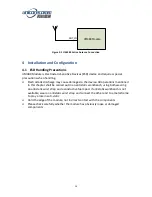
The module has the antenna input pin ANT_IN. It provides a +3.3V antenna feed, when
an active antenna of +3.3~5V is adopted, please make sure the 50 Ω antenna impedance
is matched.

