10
Technical Specifications
UC-00-M51 EN R1.0
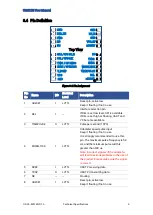
Pin
No
Name
I/O
Electrical
Level
Description
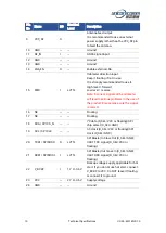
9
VCC_RF
O
Antenna feed output.
It is recommended to use an external
power supply rather than the VCC_RF pin
to feed the antenna.
10
GND
—
—
Ground
11
RF_IN
I
—
GNSS signal input
12
GND
—
—
Ground
13
GND
—
—
Ground
14
LNA_EN
O
—
Enable external LNA
15
FWD
I
LVTTL
16
NC
—
—
Floating
17
NC
—
—
Floating
18
SDA / SPI CS_N
—
—
I
2
C data (D_SEL=VCC or floating)/SPI
chip select (D_SEL=GND)
19
SCL / SPI CLK
—
—
I
2
C clock (D_SEL=VCC or floating)/SPI
clock (D_SEL=GND)
20
TXD1/ SPI MISO
O
LVTTL
SPI Master In Slave Out (D_SEL=GND);
UART TXD signal (D_SEL=VCC or
floating)
21
RXD1/ SPI MOSI
I
LVTTL
SPI Master Out Slave In (D_SEL=GND);
UART RXD signal (D_SEL=VCC or
floating)
22
V_BCKP
I
1.7 V~3.6 V
Backup voltage supply, applicable for hot
start. If you do not use hot start, connect
V_BCKP to VCC. Do NOT leave it floating
or connect it to ground.
23
VCC
—
2.7 V~3.6 V
Supply voltage
24
GND
—
—
Ground
Odometer direction input.
Keep it floating
if not in use.
It is strongly recommended to use
it.
High level
=
forward
Low level
=
reverse
Note: Incorrect signals of the odometer
will lead to serious problems in the use of
the product. Please make sure the signal
is correct.

