background image

UM621N User Manual


UC-00-M51 EN R1.0 

Clean 

13 

5


Clean 

DO NOT use alcohol or other organic solvents to clean, which may lead to soldering 

flux residues flooding into the shielding shell, causing mildew and other problems. 

6


Reflow Soldering 

In order to avoid the device falling off, the module should be placed on the top of the 

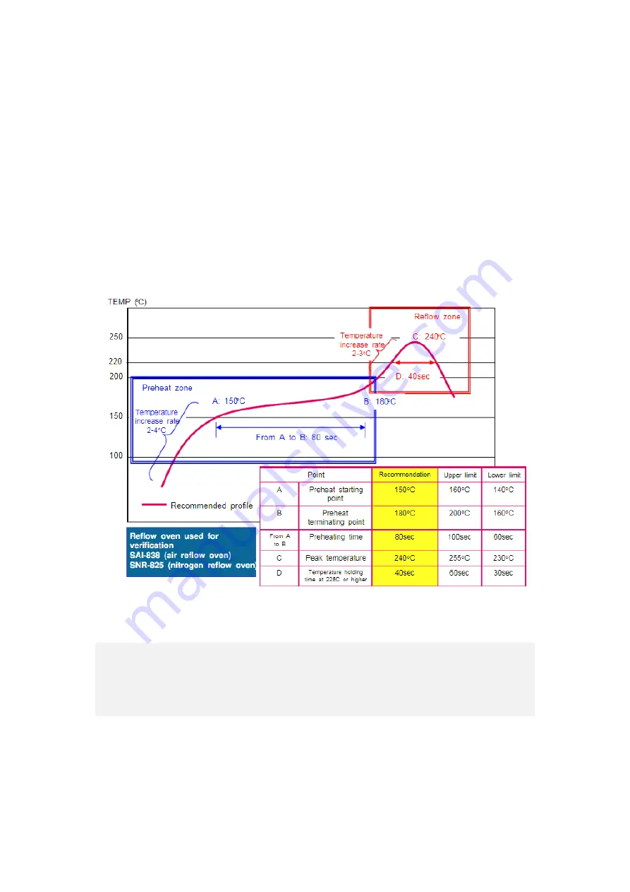
main board during soldering. Reflow soldering temperature curve is recommended as 

shown in figure 6-1 below (M705-GRN360 is recommended for solder paste).  

Note: The module can only be soldered once. 


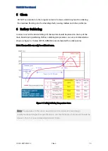
Figure 6-1 Reflow Soldering Temperature Curve 


Note: The apertures in the stencil need to meet the customer's own design 

requirements and inspection specifications, and the thickness of the stencil should be 

above 0.15 mm. It is recommended to be 0.18 mm.  

Summary of Contents for UM621N

Page 1: ...AND OPERATION USER MANUAL WWW UNICORECOMM COM Copyright 2009 2022 Unicore Communications Inc Data subject to change without notice UM621N Automotive Grade Dual frequency Multi GNSS Integrated Positio...

Page 2: ...l not be deemed as either expressly implied by estoppel or any other form the granting or transferring of Unicore rights and or interests including but not limited to the aforementioned trademark righ...

Page 3: ...ument describes the information of the hardware installation specification and the use of Unicore UM621N modules Document Structure 1 Product introduction 2 Installation guide 3 Technical specificatio...

Page 4: ...eparations 5 2 2 Hardware Installation 6 3 Technical Specifications 7 3 1 Electrical Specifications 7 3 2 Operational Conditions 7 3 3 Dimensions 8 3 4 Pin Definition 9 3 5 PCB Packaging 11 4 Package...

Page 5: ...y joint positioning and single system standalone positioning and can output GNSS MEMS combined positioning results continuously even in tunnels and underground garages The chip of UM621N conforms to t...

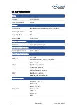
Page 6: ...tics Dimensions 16 0 mm 12 2 mm 2 4 mm Environmental Specification Operating Temperature 40 C 85 C Input Output Data Interface UART x 2 LVTTL level Supported baud rate 115200 460800 bps I2 C x 1 Addre...

Page 7: ...ation open sky Velocity Accuracy RMS 0 1 m s INS Positioning Error 3D gyro 3D accelerometer speed signal 2 Sensitivity GNSS Tracking 165 dBm Acquisition 148 dBm Hot Start 158 dBm Reacquisition 160 dBm...

Page 8: ...ternal processor for firmware upgrade UART2 only supports data transmission and can t be used for firmware upgrade MEMS UM621N integrates a six axis MEMS a three axis gyro and a three axis accelerator...

Page 9: ...nch using an antistatic wristband and a conductive foam pad If the antistatic workbench is unavailable wear an antistatic wristband and connect the other end to a metal frame to play a role in antista...

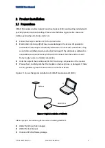
Page 10: ...Make sure to take full anti static measures such as wearing an anti static wristband and grounding the workbench Step 2 Open the UM621N evaluation kit and take out the evaluation board Step 3 Use the...

Page 11: ...Bm Maximum input power of antenna Storage Temperature TSTG 40 85 C Storage temperature for the module 3 2 Operational Conditions Item Symbol Min Typical Max Unit Condition Power Supply VCC VCC 2 7 3 3...

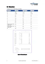
Page 12: ...follows Parameter Min mm Typical mm Max mm A 15 9 16 0 16 5 B 12 05 12 2 12 35 C 2 2 2 4 2 6 D 0 9 1 0 1 3 E 1 0 1 1 1 2 F 2 9 3 0 3 1 G 0 9 1 0 1 3 H 0 7 0 8 0 9 K Outer edge of the stamp hole 0 7 0...

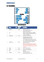
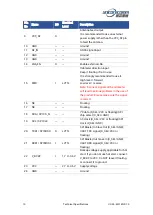
Page 13: ...erface selection pin If DEL is set low level SPI is available If DEL is set high or floating UART and I2 C become available 3 TIMEPULSE O LVTTL Pulse per second 1PPS 4 WHEELTICK I LVTTL Odometer speed...

Page 14: ...clock D_SEL GND 20 TXD1 SPI MISO O LVTTL SPI Master In Slave Out D_SEL GND UART TXD signal D_SEL VCC or floating 21 RXD1 SPI MOSI I LVTTL SPI Master Out Slave In D_SEL GND UART RXD signal D_SEL VCC o...

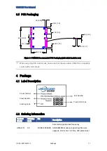
Page 15: ...hen designing PCB solder mask make sure that the area under UM621N is completely coated with solder mask 4 Package 4 1 Label Description 4 2 Ordering Information Product Model Ordering Code PN Descrip...

Page 16: ...n only withstand the temperature of 55 degrees Celsius modules shall be removed from the package during baking Figure 4 1 UM621N Module Package Item Description Number of Modules 500 pieces reel Reel...

Page 17: ...dule should be placed on the top of the main board during soldering Reflow soldering temperature curve is recommended as shown in figure 6 1 below M705 GRN360 is recommended for solder paste Note The...

Page 18: ...Unicore Communications Inc 7 F3 No 7 Fengxian East Road Haidian Beijing P R China 100094 www unicorecomm com Phone 86 10 69939800 Fax 86 10 69939888 info unicorecomm com...

Reviews: