User’s Manual
21
JP13: Voltage selector for COM3, COM4
COM3
COM4
Description
JP13
Close 1-2
Close 7-8
+12V
JP13
Close 3-4
Close 9-10
STD. RI. (RS-232)
JP13
Close 5-6
Close 11-12
+5V
JP6, JP7, JP4: RS232 / 485 Selector for COM2
TYPE JP6
JP7
JP4
RS-232 *
1-2
Open
1-2, 4-5, 7-8, 10-11
RS-485
3-4
Close
2-3, 5-6, 8-9, 11-12
*
Make sure the port mode is set up correctly before installing any
peripherals.
JP3: On-board Power Good Selector
JP3
Function
Pin 1-2
Using External Power Good
Pin 2-3 *
Using On Board Power Good
FAN1, FAN2: CPU / 2nd Cooling Fan Connector
Pin No.
Function
Pin 1
Sensor Pin.
Pin 2
+12V
Pin 3
GND
JP24; J2’s Pin 19~21: Power Supply Type
Power Type
JP24
J2’s Pin 19~21
PS/2 AT
Close 2-3
Close 19-20
ATX
Close 1-2
Close 20-21
J2’s Pin15,16: For ATX Power Supply On/Off
Pin 15; Pin 16 On/Off Switch for ATX Power Button
22
The ENDAT-3701/3702/3902 All-In-One motherboard
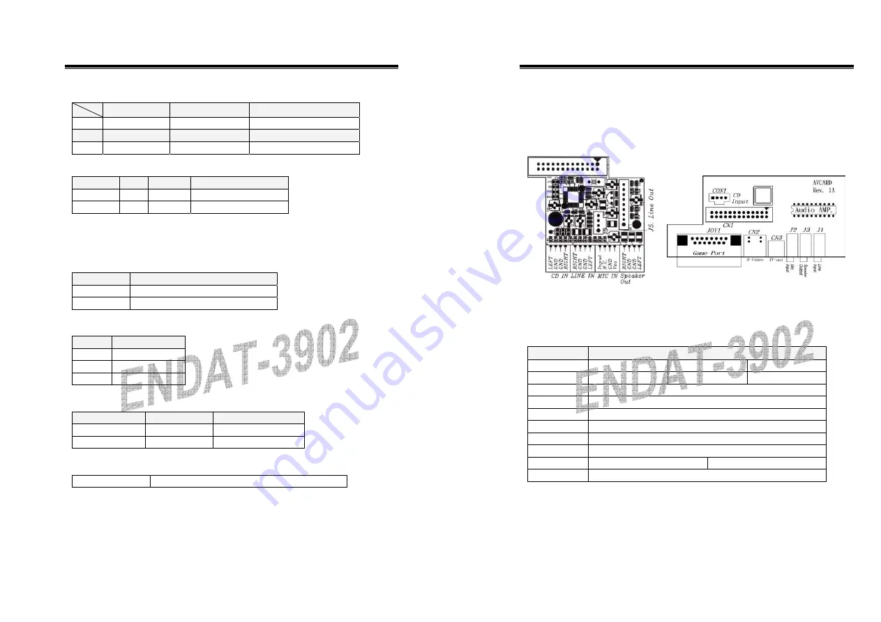
CN6: Audio Output Port connector via AV Card Kit
(Optional)
The AV Card Kit Adapter supports Sound, Game Port. Please close
pin13-14 to disable onboard Audio features if the AV Card Kit is not
inserted onto the
CN6
connector.
UC-A001
AV Card
J2: Case Panel connection
Pin No.
Description
1, 2
IDE 1 LED
Pin 1 =
–
Pin 2 = +
3, 4
IDE 2 LED
Pin 3 =
–
Pin 4 = +
5, 8
External Speaker
6, 7
Onboard Buzzer
9, 10
Reset Switch
13,14 Power
LED
Indicator
15, 16
Power On/Off Switch (for ATX Power only)
17, 18
Turbo LED(for case only, no function)
19, 20, 21
19-20 for AT Power
20-21 for ATX Power
22, 23
Modem Ring Detected / Wake on LAN


