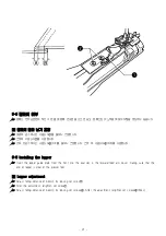
- 17 -
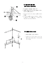
9-2 Need le and looper timing adjustment
☞
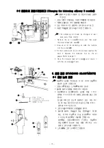
Make an adjustment so that, when needles① are down lowest loopers② reach the end of their backward travel and
the distance from the needle center to the looper tip is 3mm.
1. Turn the set screws③(2pcs)m and then open the belt cover plate④
2. Turn the pulley toward yourself until loopers②reach the end of their backward travel.
3. Loosen cap screw⑤, and then loosen set screws⑦(2pcs) on lower belt wheel⑥.
4. Turn the pullwe toward yourself until needles① come down to the lowest position.
5. Tighten set screws⑦(2pcs) securely, and then tighten cap screw⑤.
6. Loosen set screws⑧(2pcs), move looper holder⑨ in the arrow direction until the distance between the needle center
and the looper tip is 3mm, and tighten set screws⑧ securely.
7. Make sure that the looper thread eyes match the needle eyes in the forward and backward travels of the loopers.
8 Close the belt cover plate④, and then tighten set screws③(2pcs).
9 Install the presser foot, needle plate and feeddogs.
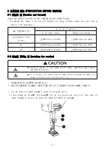
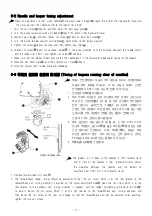
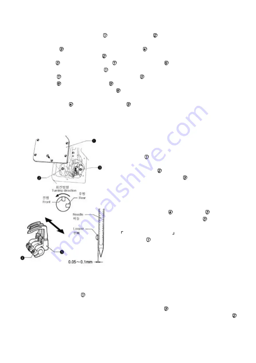
9-3 루퍼의 침회피 운동의 타 이밍 (Tim ing of loopers running clear of needles)
☞
루퍼는 전진행정에서 바늘의 뒤쪽 방향을 지나서, 후진행정에서
바늘의 앞쪽 방향을 지납니다. 이 때, 바늘과 루퍼의 간격은
전진행정에서 0.05~1mm로 되도록 조정하여 주십시오.
1. 전 이송완카바①를 분해합니다.
2. 루퍼 전후의 타이밍은 상하 편심륜의 회전 방향의 고정나사가
루퍼 연간 조정구멍②과 일치할 때, 전후 편심륜의 회전방향의
전방 고정나사 슬리브조정 구멍③과 일치되도록 조절합니다.
조절은 전후 편심륜의 회전 방향의 후방고정 나사를 풀고 전방
고정나사를 전후 편심륜이 조절될 정도 풀어서 조절합니다.
조절 후 2개의 고정나사를 체결합니다.
3. 루퍼 끝단면이 바늘 중심에 일치할 때, 간격이 0.05~0.1mm로
되도록 루퍼잡이 고정나사④를 풀고, 루퍼잡이⑤를 화살표 방향
으로 움직여서 조정합니다. 이때, 루퍼잡이⑤는 화살표 방향
이외로 움직이지 않게 하여 주십시오. 만약 움직이는 경우는
「9-2바늘과 루퍼 타이밍조정」을 행하여 주십시오.
4. 루빠이송암덮개①를 조립합니다.
☞
The loopers run in back of the needles in their forward travel
and in front of the needles in their backward travel. Adjust
the clearance between the needles and the loopers to
anywhere from 0.05-1mm in the forward travel.
1. Remove forward feed arm cover①.
2. The forward/back looper timing should be adjusted so that the set screw which is at the rear relative to the
forward/back cam turning direction is aligned wit the screw adjustment hole③ when the set screw which is at the
rear relative to the up/down cam turning direction is aligned with the looper connecting rod adjustment hole②.
To adjust, loosen the set screw which is at the fron relative to the forward/back cam turning direction, and
then loosen the set screw at the rear just enough so that the forward/back cam can be adjusted. After adjusting,
tighten the two set screws.
Summary of Contents for DT6-H892?3
Page 2: ......
Page 4: ...5 off A S 31 2 40 25 OFF A S A S...
Page 32: ...22 10 1 13 19 2 9 16 16 20 16 3 13 19 4 19 13...

