9
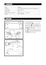
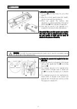
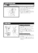
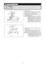
1)
Loosen nut
➋
, As you turn presser spring
regulator clockwise (in direction
Ⓐ
), the
presser foot pressure will be increased.
2)
As you turn the presser spring regulator
counterclockwise (in direction
Ⓑ
), the pressure
will be decreased.
3)
After adjustment, tighten nut
➋
4)
For general fabrics, the standard height of the
presser spring regulator is 29 to 32 mm (5kg)
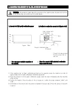
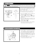
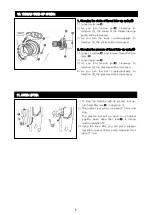
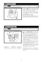
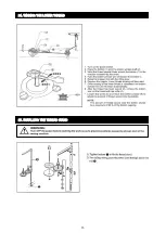
1)
Loosen screws
➋
and
➌
feed eccentric cam
➊
move the feed eccentric cam in the
direction of the arrow or opposite direction of
the arrow, and firmly tighten the screws.
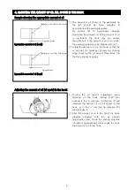
2)
For the standard adjustment, adjust so that the
top surface of feed dog and the top end of
needle eyelet are flush with the top surface of
throat plate when the feed dog descends
below the throat plate.
3)
To advance the feed timing in order to prevent
uneven material feed, move the feed eccentric
cam in the direction of the arrow.
4)
To delay the feed timing in order to increase
stitch tightness move the feed eccentric cam in
the opposite direction from the arrow.
CAUTION: Be careful not to move the feed
eccentric cam too far, or else needle breadage
may result.
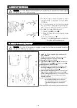
12. PRESSER FOOT PRESSURE
WARNING Turn OFF the power before starting the work so as to prevent a accidents caused
by abrupt start of the sewing machine.
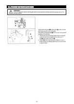
WARNING Turn OFF the power before starting the work so as to prevent a accidents caused
by abrupt start of the sewing machine.
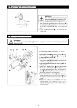
13. ADJUSTING THE FEED TIMING
Summary of Contents for H5600-D
Page 1: ......
Page 16: ...12 19 ATTACHING THE CLOTH CUTTING KNIFE 20 CHANGING THE CUTTING WIDTH...
Page 17: ...13 21 ADJUSTING THE KNIFE COMPONENTS 22 ADJUSTING THE HEIGHT OF THE KNEE LIFTER...
Page 18: ...14 23 OTHER REPLACEMENT PARTS...
Page 19: ...15 24 WINDING THE LOWER THREAD 25 INSTALLING THE THREAD STAND...
Page 20: ...16 26 ATTACHING THE WASTE CLOTH GUIDE...
Page 21: ......
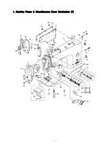
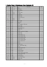
Page 22: ...1 1 Machine Frame Miscellaneous Cover Mechanism 1...
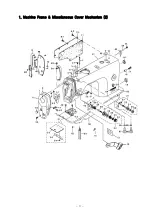
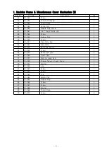
Page 24: ...3 1 Machine Frame Miscellaneous Cover Mechanism 2...
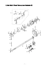
Page 26: ...5 2 Main Shaft Thread Take up Lever Mechanism 1...
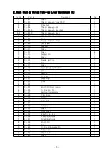
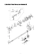
Page 28: ...7 2 Main Shaft Thread Take up Lever Mechanism 2...
Page 30: ...9 3 Needle Bar Vertical Shaft Hook Driving Shaft Mechanism...
Page 32: ...11 4 Hand Lifter Mechanism...
Page 34: ...13 5 Feed Mechanism 1...
Page 36: ...15 5 Feed Mechanism 2...
Page 38: ...17 6 Thread Trimmer Mechanism...
Page 40: ...19 7 Automatic Reverse Feed Mechanism...
Page 42: ...21 8 Oil Lubrication Mechanism Bobbin Mechanism...
Page 44: ...23 9 Oil Pan Mechanism...
Page 49: ......


