background image

모델/Modal

LS2-H550

LS2-H5500

용도/Application

중후물/Medium materials

미싱회전수/Max. Sewing speed

5000 spm

최대땀길이/Max. Stitch length

5.4 mm

톱니높이/Feed dog height

0.8 mm

최대노루발높이/

Max.Presser foot height

무릎올림/Using knee

13 mm

올림대/presser bar lifter

6 mm

바늘/Needle type

DB

× 

1#14(#11

#18)

노루발압/Presser foot pressure

3

8 Kg

침봉운동량/Needle stroke

31 mm

천평운동량/Thread take-up lever stroke

59.3 mm

급유방식/Lubrication system

완전자동급유방식/Automatic lubrication

베드사이즈/Bed size

476

× 

178 mm

작업범위/Arm pocket size

266.5

× 

134.5 mm

재단폭/Cutting width

3.2 mm (1/8") 

∼ 

9.5 mm (3/8")

-  1  -

미싱의  사양

1

※ 

그 외 시리즈로(Other series) 4mm(5/32"), 4.8mm(3/16"), 5.6mm(7/32"), 6.4mm(1/4") 

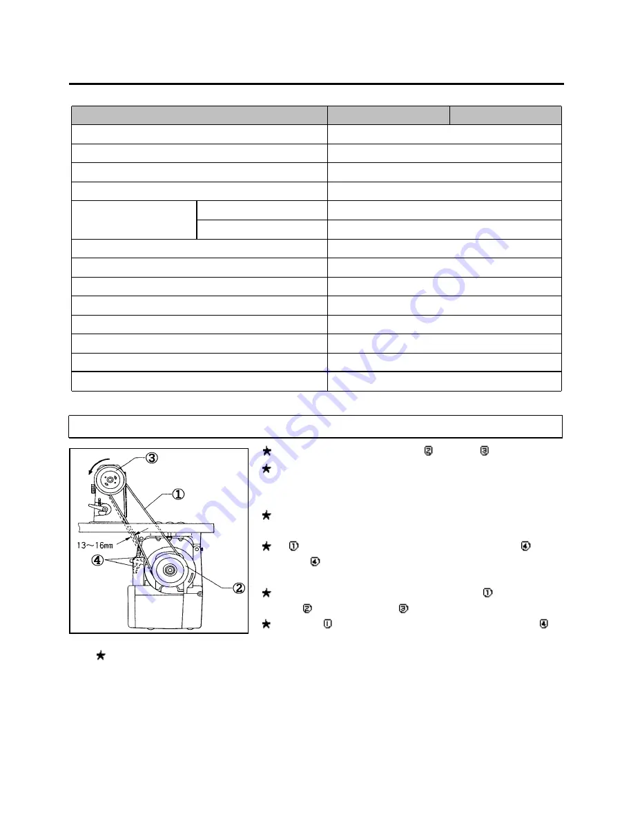
1.  벨트  거는  방법  /  How  to  install  the  belt


★미싱을 뒤로 눕혀서 V벨트를 모터풀리②와 미싱풀리③에 걸어 주십시오.

   ★벨트의 장력은 출하시 적정한 장력으로 조정되어 있습니다. 

     어느 정도 사용하게 되면 V벨트가 풀리에 길들여져서 벨트의 장력이

     느슨해질 경우가 있으므로 벨트의 장력을 확인하여 주십시오.

   ★미싱의 회전방향은 풀리쪽에서 볼 때 좌회전입니다. 

     (시계반대 방향입니다.)

   ★벨트①을 손으로 눌려 13mm

16mm 눌려질 정도로 고정나사④를 

     풀고 너트④을 돌려서 조절하십시오.

   ★ Tilt  back the machine  head and place the  belt ①  onto the motor    

      pulley ② and machine pulley ③.

   ★  Press  belt  ①  with  a  finger  (force  of  5  N),  and  adjust  the  nut④  so     

                                             that there is a deflection of 13 to 16 mm.

Note: ★ While using the machine, the belt will conform to the pulley  and cause the belt tension to loosen. If the belt  

         tension is too loose the following faults could occur.

           a. The stopping position may shift,

           b. The needle bar may drift when the machine stops,

           c. An extra stitch may be sewing when the machine stops,

           d. An abnormal noise may be head due to belt slipping, and

           e. The belt may become too loose and contact with the cover.

All manuals and user guides at all-guides.com

all-guides.com

Summary of Contents for LS2-H550

Page 1: ...1 OPERATION MANUAL PART BOOK LS2 H550 LS2 H5500 SINGLE NEEDLE FEED LOCKSTITCH WITH SIDE CUTTER SEWING MACHINE WITH THREAD TRIMMER All manuals and user guides at all guides com a l l g u i d e s c o m...

Page 2: ...All manuals and user guides at all guides com...

Page 3: ...eware of injury This symbol indicates something that you must not do This symbol indicates something that you must do The picture inside the circle indicates the nature of the thing that must be done...

Page 4: ...5 off A S 31 2 40 25 OFF A S A S All manuals and user guides at all guides com...

Page 5: ...overs to the machine head and motor Be sure to wear protective goggles and gloves when handling the lubricating oil and grease so that they do not get into your eyes or onto your skin otherwise inflam...

Page 6: ...not using the machine and when leaving the machine unattended For machines with automatic presser lifter do not touch the solenoid section because if becomes hot during operation and may cause severe...

Page 7: ...y maintenance and inspection of the electrical system Turn off the power switch and disconnect the power cord from the wall outlet at the following times otherwise the machine may operate if the tread...

Page 8: ...N dealer The positions of the labels may vary slightly depending on the model of sewing machine or motor 1 2 Be sure to connect the ground If the ground connection is not secure you run a high risk of...

Page 9: ...rned on verify the rotational direction of the pulley with the power on The pulley should rotate counterclockwise when viewed from the pulley Power must be turned off when the machine is not in use or...

Page 10: ...8 4 Needle feed mechanism 8 5 Feed regulation mechanism 9 6 Thread wiper 9 7 Knife mechanism 10 8 Thread trimmer 11 14 ADJUSTMENT 15 24 1 Adjusting the needle bar height 15 2 Adjusting the rotary hook...

Page 11: ...l the belt V V 13mm 16mm Tilt back the machine head and place the belt onto the motor pulley and machine pulley Press belt with a finger force of 5 N and adjust the nut so that there is a deflection o...

Page 12: ...off any contamination from the magnet and the oil pan Use the oil specified by Spindle15 2 Adjusting lubrication for upper shaft and rotary hook 1 1 Upper shaft lubrication Remove the face plate and...

Page 13: ...e needle plate 2 Upper knife operation To operate the upper knife lower the upper knife set lever The upper knife will now operate in sync with the operation of the machine To stop the upper knife rai...

Page 14: ...needle DB 1 Insert the needle completely making sure that the lengthwise groove of the needle is on the left and secure it using the set screw Use a DBx1 needle 4 Threading the needle All manuals and...

Page 15: ...3 Pull the thread from the bobbin case tension spring 6 Winding the bobbin thread 1 2 3 4 1 Fit the bobbin in the bobbin winder shaft 2 Depress the joint as far as it will go 3 Wind the bobbin thread...

Page 16: ...djust the operation range of the thread take up spring loosen the set screw and turn the thread tension bracket assembly To adjust the tension of the thread take up spring fit a screwdriver into the s...

Page 17: ...mp moves the needle bar vertically 4 The needle bar is guided by the needle bar bracket 2 Lower shaft and rotary hook mechanism 1 2 3 1 When the pulley turns in the direction of the arrow the bevel ge...

Page 18: ...eed rocker shaft and the feed rocker bracket arm 5 When the inclination of the feed regulator and the pivot point of the level feed link change the horizontal momentum of the level feed arm link chang...

Page 19: ...nclination decides the feed amount of the feed rocker mechanism and the needle bar mechanism Pressing the reverse lever reverses the inclination of the feed regulator to feed the material in reverse 1...

Page 20: ...tric wheel with the screw moves vertically at the cam part eccentric part of the thread take up crank assembly 4 The knife driving link the knife driving rod and the knife shaft clamp assembly attache...

Page 21: ...figures show the thread trimmer without the rotary hook assembly 1 During operation The thread trimmer cam lever spring presses the thread trimmer cam lever assembly against the thread trimmer soleno...

Page 22: ...of the thread trimming clutch 3 Movable knife holder action Due to the rotation of the lower shaft the thread trimmer clutch pushes the roller shaft up The motion of the roller shaft is transmitted t...

Page 23: ...he thread trimmer clutch and returns to its original position The thread trimmer lever spring returns the thread trimmer rod and the movable knife holder to their original positions in the direction o...

Page 24: ...tly above its lowest position the upper shaft has turned approximately 330 and the needle thread is spread by the movable knife as shown in the figure above If the timing of the movement is too early...

Page 25: ...h Then firmly tighten the screw A 0 0 5mm 0 0 05mm Align the bottom reference line of the needle bar with surface A of the needle bar oil rejector needle bar bush by turning the machine pulley slowly...

Page 26: ...icated below For thin materials The needle tip is aligned with tips of the feed dog and the upper surface of the needle plate For thick materials There is a 5mm gap between the needle tip and the uppe...

Page 27: ...ew of the needle feed arm then move the needle bar bracket forward or backward 2 Feed dog position Set the feed regulating dial to maximum and turn the machine pulley Check that the needle enters the...

Page 28: ...0Kg 1 Loosen the screw and turn the machine pulley until the needle bar is raised 5 mm above its lowest position then depress the thread trimming solenoid 2 With the thread trimming solenoid depressed...

Page 29: ...thread trimming clutch 3 With the thread trimming solenoid depressed turn the machine pulley Adjust the movable knife and the fixed knife so that they overlap when the rotation of thread trimming clut...

Page 30: ...or down 1 2 2 90 1 When the feed dog is fully raised its angle is properly adjusted if the circle on the feed bracket shaft aligns with the index on the feed rock shaft arm 2 To adjust the feed dog an...

Page 31: ...ed 215 spm 3 Adjust as follows when the forward and backward stitch lengths are different 1 Remove the rear plate 2 Loosen the screw 3 When the forward stitch length is greater than the backward set t...

Page 32: ...ould be a 9 5 11 5 mm gap between the upper surface of the needle plate and the needle tip with thin or medium materials or a 10 12 mm gap with thick materials If adjustment of needle stop position is...

Page 33: ...using the presser bar lifter 2 Remove the screw and the needle plate 3 Remove the screws and the feed dog 4 Remove the screws and the auxiliary needle plate 5 Turn the machine pulley until the needle...

Page 34: ...he back edge pf the upper knife should be aligned with the needle center The upper knife can be adjusted by loosening the screw and moving the knife within a range of 2 mm forward to 3 mm backward 3 U...

Page 35: ...25 4 4 16 15 15 15 4 4 4 6 6 6 2 All manuals and user guides at all guides com...

Page 36: ...igh Thread wiper position Adjust thread wiper position with screw Thread breakage Improper threading Threading Rethread 4 Bent needle Blunt needle tip jammed eye Needle Replace needle 4 Improper needl...

Page 37: ...27 4 4 1 4 4 15 15 15 6 6 All manuals and user guides at all guides com...

Page 38: ...ser bar pressure Tighten presser foot adjustment screw Presser bar height Adjust presser bar height Improper needle to rotary hook timing Needle bar rise Adjust needle to rotary hook timing 15 Needle...

Page 39: ...29 6 6 6 6 puff 15 19 23 4 22 19 23 19 All manuals and user guides at all guides com...

Page 40: ...ap Adjust needle to rotary hook timing 15 Improper thread cutting a Needle bobbin threads not cut b Needle thread not cut c Bobbin thread not cut Movable knife fixed knife do not overlap Adjust knives...

Page 41: ...31 6 1 22 6 24 24 24 24 All manuals and user guides at all guides com a l l g u i d e s c o m...

Page 42: ...transmitted Check circuits refer to motor adjustment manual Thread wiper does not function Needle thread remainder too long Adjust pretension 6 Timing too early wipes thread before tension disc closes...

Page 43: ...33 All manuals and user guides at all guides com...

Reviews: