background image

-  3  -

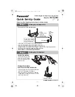
1.  발판조작  /  Pedal  operation

올바른  사용방법  /  OPERATION

★ 발판을 가볍게 ①까지 밟아서 저속재봉을 확인해주십시오. ②까지 밟으면 고속재봉을 합니다.

★ 발판을 앞으로 밟은후 중립(발판에서 발을 때었을때)③이 되면 바늘이 침판에서 내려간 위치에서 정지하는 것을 확인해주십시오.

    (침하정지를 설정한 경우)

★ 발판을 ④쪽으로 역으로 밟으면(또는 발판을 ④쪽으로 역으로 밟은후, 중립③으로 돌아온 경우) 사절후 바늘이 침판에서 올라간 위치에서 정지합니다.

★ Treadle the pedal lightly to position① and that the machine sews at low speed. Then treadle the pedal to position② to sew at   

   high speed.

★ After treading the pedal, return it to neutral③ (simply release the pedal) to stop the machine with the needle tip below the needle  

   plate(when the needle position switch is set to the needle down position).

★ Back-treadle  the pedal to  position④ and release it to  neutral  to trim the  thread  and  stop  the machine  with  the needle raised     

    above the needle plate.

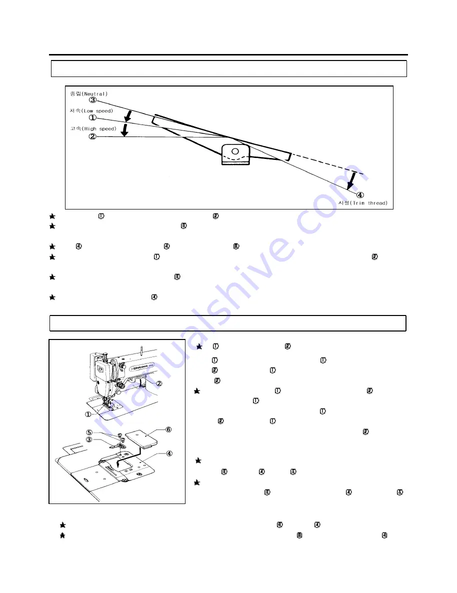
2.  윗칼조작  /  Upper  knife  operation


★윗칼①을 작동시킬 경우는 레버②를 내려주세요.

     윗칼①은 미싱운전과 동시에 동작합니다. 윗칼①을 고정시킬 경우는

     레버②를 올려부세요. 윗칼①은 올라갑니다. 


※ 

레버②의 조작은 반드시 미싱을 정지시킨후 해주세요

   ★ To operate the upper knife①, lower the upper knife set lever②. 

       The  upper  knife①  will  now  operate  in  sync  with  the  operation  of         

       the  machine.  To  stop  the  upper  knife①,  raise  the  upper  knife  set         

       lever②. The upper knife① will rise.


※ 

Stop the machine before operating the upper knife set lever②.


ꁴ 

안내U의  설치방법 (Attaching the s ewing s crap guide(U)


 ★ 짤려진 천조각이 베드이 하측으로 떨어짐이 어려울 때는, 부속의 

       안내U③을 보조침판④에 죔나사⑤로 설치해주세요.

   ★ When it  is  difficult for scraps  to drop  below the bed, attach  the supplied    

       sewing scrap guide(U)③ to the auxiliary needle plate④ using the screw⑤.


침판덮 개의 설치방법 (Ins ta ll ing the needl e pla te cover)

★ 재단한 천조각을 베드 아래면에 떨어뜨릴 필요가 없는 경우는, 부속의 침판덮개⑥를 보조침판④에 끼워서 사용해주세요.

★ If it is not necessary to collect scraps below the bed, fit the supplied needle plate cover⑥ over the auxiliary needle plate④.

All manuals and user guides at all-guides.com

Summary of Contents for LS2-H550

Page 1: ...1 OPERATION MANUAL PART BOOK LS2 H550 LS2 H5500 SINGLE NEEDLE FEED LOCKSTITCH WITH SIDE CUTTER SEWING MACHINE WITH THREAD TRIMMER All manuals and user guides at all guides com a l l g u i d e s c o m...

Page 2: ...All manuals and user guides at all guides com...

Page 3: ...eware of injury This symbol indicates something that you must not do This symbol indicates something that you must do The picture inside the circle indicates the nature of the thing that must be done...

Page 4: ...5 off A S 31 2 40 25 OFF A S A S All manuals and user guides at all guides com...

Page 5: ...overs to the machine head and motor Be sure to wear protective goggles and gloves when handling the lubricating oil and grease so that they do not get into your eyes or onto your skin otherwise inflam...

Page 6: ...not using the machine and when leaving the machine unattended For machines with automatic presser lifter do not touch the solenoid section because if becomes hot during operation and may cause severe...

Page 7: ...y maintenance and inspection of the electrical system Turn off the power switch and disconnect the power cord from the wall outlet at the following times otherwise the machine may operate if the tread...

Page 8: ...N dealer The positions of the labels may vary slightly depending on the model of sewing machine or motor 1 2 Be sure to connect the ground If the ground connection is not secure you run a high risk of...

Page 9: ...rned on verify the rotational direction of the pulley with the power on The pulley should rotate counterclockwise when viewed from the pulley Power must be turned off when the machine is not in use or...

Page 10: ...8 4 Needle feed mechanism 8 5 Feed regulation mechanism 9 6 Thread wiper 9 7 Knife mechanism 10 8 Thread trimmer 11 14 ADJUSTMENT 15 24 1 Adjusting the needle bar height 15 2 Adjusting the rotary hook...

Page 11: ...l the belt V V 13mm 16mm Tilt back the machine head and place the belt onto the motor pulley and machine pulley Press belt with a finger force of 5 N and adjust the nut so that there is a deflection o...

Page 12: ...off any contamination from the magnet and the oil pan Use the oil specified by Spindle15 2 Adjusting lubrication for upper shaft and rotary hook 1 1 Upper shaft lubrication Remove the face plate and...

Page 13: ...e needle plate 2 Upper knife operation To operate the upper knife lower the upper knife set lever The upper knife will now operate in sync with the operation of the machine To stop the upper knife rai...

Page 14: ...needle DB 1 Insert the needle completely making sure that the lengthwise groove of the needle is on the left and secure it using the set screw Use a DBx1 needle 4 Threading the needle All manuals and...

Page 15: ...3 Pull the thread from the bobbin case tension spring 6 Winding the bobbin thread 1 2 3 4 1 Fit the bobbin in the bobbin winder shaft 2 Depress the joint as far as it will go 3 Wind the bobbin thread...

Page 16: ...djust the operation range of the thread take up spring loosen the set screw and turn the thread tension bracket assembly To adjust the tension of the thread take up spring fit a screwdriver into the s...

Page 17: ...mp moves the needle bar vertically 4 The needle bar is guided by the needle bar bracket 2 Lower shaft and rotary hook mechanism 1 2 3 1 When the pulley turns in the direction of the arrow the bevel ge...

Page 18: ...eed rocker shaft and the feed rocker bracket arm 5 When the inclination of the feed regulator and the pivot point of the level feed link change the horizontal momentum of the level feed arm link chang...

Page 19: ...nclination decides the feed amount of the feed rocker mechanism and the needle bar mechanism Pressing the reverse lever reverses the inclination of the feed regulator to feed the material in reverse 1...

Page 20: ...tric wheel with the screw moves vertically at the cam part eccentric part of the thread take up crank assembly 4 The knife driving link the knife driving rod and the knife shaft clamp assembly attache...

Page 21: ...figures show the thread trimmer without the rotary hook assembly 1 During operation The thread trimmer cam lever spring presses the thread trimmer cam lever assembly against the thread trimmer soleno...

Page 22: ...of the thread trimming clutch 3 Movable knife holder action Due to the rotation of the lower shaft the thread trimmer clutch pushes the roller shaft up The motion of the roller shaft is transmitted t...

Page 23: ...he thread trimmer clutch and returns to its original position The thread trimmer lever spring returns the thread trimmer rod and the movable knife holder to their original positions in the direction o...

Page 24: ...tly above its lowest position the upper shaft has turned approximately 330 and the needle thread is spread by the movable knife as shown in the figure above If the timing of the movement is too early...

Page 25: ...h Then firmly tighten the screw A 0 0 5mm 0 0 05mm Align the bottom reference line of the needle bar with surface A of the needle bar oil rejector needle bar bush by turning the machine pulley slowly...

Page 26: ...icated below For thin materials The needle tip is aligned with tips of the feed dog and the upper surface of the needle plate For thick materials There is a 5mm gap between the needle tip and the uppe...

Page 27: ...ew of the needle feed arm then move the needle bar bracket forward or backward 2 Feed dog position Set the feed regulating dial to maximum and turn the machine pulley Check that the needle enters the...

Page 28: ...0Kg 1 Loosen the screw and turn the machine pulley until the needle bar is raised 5 mm above its lowest position then depress the thread trimming solenoid 2 With the thread trimming solenoid depressed...

Page 29: ...thread trimming clutch 3 With the thread trimming solenoid depressed turn the machine pulley Adjust the movable knife and the fixed knife so that they overlap when the rotation of thread trimming clut...

Page 30: ...or down 1 2 2 90 1 When the feed dog is fully raised its angle is properly adjusted if the circle on the feed bracket shaft aligns with the index on the feed rock shaft arm 2 To adjust the feed dog an...

Page 31: ...ed 215 spm 3 Adjust as follows when the forward and backward stitch lengths are different 1 Remove the rear plate 2 Loosen the screw 3 When the forward stitch length is greater than the backward set t...

Page 32: ...ould be a 9 5 11 5 mm gap between the upper surface of the needle plate and the needle tip with thin or medium materials or a 10 12 mm gap with thick materials If adjustment of needle stop position is...

Page 33: ...using the presser bar lifter 2 Remove the screw and the needle plate 3 Remove the screws and the feed dog 4 Remove the screws and the auxiliary needle plate 5 Turn the machine pulley until the needle...

Page 34: ...he back edge pf the upper knife should be aligned with the needle center The upper knife can be adjusted by loosening the screw and moving the knife within a range of 2 mm forward to 3 mm backward 3 U...

Page 35: ...25 4 4 16 15 15 15 4 4 4 6 6 6 2 All manuals and user guides at all guides com...

Page 36: ...igh Thread wiper position Adjust thread wiper position with screw Thread breakage Improper threading Threading Rethread 4 Bent needle Blunt needle tip jammed eye Needle Replace needle 4 Improper needl...

Page 37: ...27 4 4 1 4 4 15 15 15 6 6 All manuals and user guides at all guides com...

Page 38: ...ser bar pressure Tighten presser foot adjustment screw Presser bar height Adjust presser bar height Improper needle to rotary hook timing Needle bar rise Adjust needle to rotary hook timing 15 Needle...

Page 39: ...29 6 6 6 6 puff 15 19 23 4 22 19 23 19 All manuals and user guides at all guides com...

Page 40: ...ap Adjust needle to rotary hook timing 15 Improper thread cutting a Needle bobbin threads not cut b Needle thread not cut c Bobbin thread not cut Movable knife fixed knife do not overlap Adjust knives...

Page 41: ...31 6 1 22 6 24 24 24 24 All manuals and user guides at all guides com a l l g u i d e s c o m...

Page 42: ...transmitted Check circuits refer to motor adjustment manual Thread wiper does not function Needle thread remainder too long Adjust pretension 6 Timing too early wipes thread before tension disc closes...

Page 43: ...33 All manuals and user guides at all guides com...

Reviews: