background image

-  6  -

올바른  사용방법  /  OPERATION

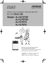
7.  사조자  /  Adjusting  the  thread  tension

★ 밑실의 상태는 실 끝을 잡았을 때, 보빈케이스가 저절로 흘러내리지 않을 정도로 약하게 나사①를 돌려서 조절해주십시오.

★ 윗실상태는 노루발을 내린 후, 나사②를 돌려서 위 그림과 같이 조절해주십시오.

★ 사절 후 바늘 끝에 남은 실의 길이는 35~40mm가 되도록 조절나사③을 돌려 조절해주십시오.

★ Adjust the bobbin thread tension by turning the adjusting screw ① so that the bobbin case will not slip down of its  

    own weight when suspended from the bobbin thread.

★ Lower the presser foot and adjust the needle thread tension by turning the adjusting screw ② as shown in figure above.

★ Adjust the adjusting screw ③ so that the length of the needle thread after thread trimming is about 35 ~ 40 mm.


ꁴ 

실잡 이 스 프링 (Threa d tak e-up spring)

  ★  실잡이스프링의  동작범위는  7~10mm가  표준입니다.  또  실잡이     

      스프링의 강함은 25~30g가 표준입니다.

  ★  실잡이스프링의  작용범위를  조절하는  것은  고정나사④을  풀고,     

      윗실조절기를 돌려주십시오.

  ★  실잡이스프링의  강함을  바꾸는  것은 사조자봉⑤의  홈에  드라이버   

      끝을 넣고 돌려서 조절해주십시오.

  ★  The  standard  operation  range  of  the  thread  take-up  spring  is     

      about 7~10mm. The standard tension at this time is 25~30g.

★ To adjust the operation range of the thread take-up spring, loosen the set screw④ and turn the thread tension bracket assembly.

★ To adjust the tension of the thread take-up spring, fit a screwdriver into the slot, and turn the tension stud ⑤ as appropriate.

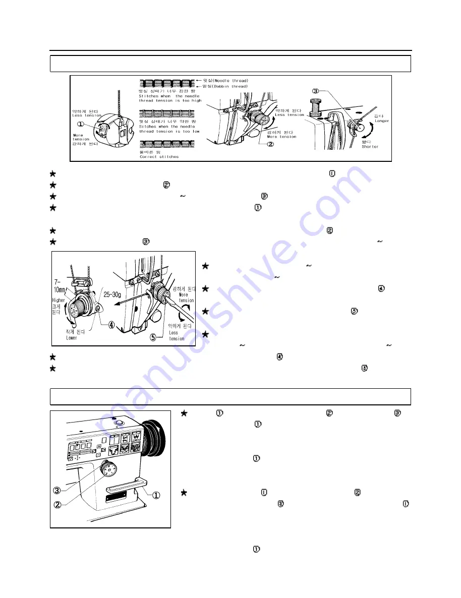
8.  땀  길이의  조절  /  Adjusting  the  stitch  length

   ★ 역전핸들①을 중앙의 위치까지 누르고, 다이얼②의 숫자를 상부의 핀③에 

      맞추고 나서 역전핸들①을 놓아주십시오.


※ 

숫자가 클수록 이송량은 많게 됩니다. 최대 땀은 5mm입니다. 단 역전재봉은 

      약3mm입니다.


ꁴ 

역전장치      역전핸들①을 누르면 천이 역이송됩니다. 놓으면 복원해서 정이송으로  

                   되는 자동복원식입니다.

   ★ Push the  reverse  lever  ① halfway down,  turn the  dial  ②  until  the  desired  

      number is aligned with the pin ③ at the top, and release the reverse lever ①.


※ 

The  larger  the  number,  the  longer  the stitch  will  be. Maximum  stitch     

       length is 5 mm. For reverse stitching, it is 3 mm

ꁴ 

Re ve rse sewin g d evice     The reverse sewing device is of the automatic-resetting type. The material will be fed  

                             backward when the reverse lever ① is pressed, and forward again when it is released.

All manuals and user guides at all-guides.com

all-guides.com

Summary of Contents for LS2-H550

Page 1: ...1 OPERATION MANUAL PART BOOK LS2 H550 LS2 H5500 SINGLE NEEDLE FEED LOCKSTITCH WITH SIDE CUTTER SEWING MACHINE WITH THREAD TRIMMER All manuals and user guides at all guides com a l l g u i d e s c o m...

Page 2: ...All manuals and user guides at all guides com...

Page 3: ...eware of injury This symbol indicates something that you must not do This symbol indicates something that you must do The picture inside the circle indicates the nature of the thing that must be done...

Page 4: ...5 off A S 31 2 40 25 OFF A S A S All manuals and user guides at all guides com...

Page 5: ...overs to the machine head and motor Be sure to wear protective goggles and gloves when handling the lubricating oil and grease so that they do not get into your eyes or onto your skin otherwise inflam...

Page 6: ...not using the machine and when leaving the machine unattended For machines with automatic presser lifter do not touch the solenoid section because if becomes hot during operation and may cause severe...

Page 7: ...y maintenance and inspection of the electrical system Turn off the power switch and disconnect the power cord from the wall outlet at the following times otherwise the machine may operate if the tread...

Page 8: ...N dealer The positions of the labels may vary slightly depending on the model of sewing machine or motor 1 2 Be sure to connect the ground If the ground connection is not secure you run a high risk of...

Page 9: ...rned on verify the rotational direction of the pulley with the power on The pulley should rotate counterclockwise when viewed from the pulley Power must be turned off when the machine is not in use or...

Page 10: ...8 4 Needle feed mechanism 8 5 Feed regulation mechanism 9 6 Thread wiper 9 7 Knife mechanism 10 8 Thread trimmer 11 14 ADJUSTMENT 15 24 1 Adjusting the needle bar height 15 2 Adjusting the rotary hook...

Page 11: ...l the belt V V 13mm 16mm Tilt back the machine head and place the belt onto the motor pulley and machine pulley Press belt with a finger force of 5 N and adjust the nut so that there is a deflection o...

Page 12: ...off any contamination from the magnet and the oil pan Use the oil specified by Spindle15 2 Adjusting lubrication for upper shaft and rotary hook 1 1 Upper shaft lubrication Remove the face plate and...

Page 13: ...e needle plate 2 Upper knife operation To operate the upper knife lower the upper knife set lever The upper knife will now operate in sync with the operation of the machine To stop the upper knife rai...

Page 14: ...needle DB 1 Insert the needle completely making sure that the lengthwise groove of the needle is on the left and secure it using the set screw Use a DBx1 needle 4 Threading the needle All manuals and...

Page 15: ...3 Pull the thread from the bobbin case tension spring 6 Winding the bobbin thread 1 2 3 4 1 Fit the bobbin in the bobbin winder shaft 2 Depress the joint as far as it will go 3 Wind the bobbin thread...

Page 16: ...djust the operation range of the thread take up spring loosen the set screw and turn the thread tension bracket assembly To adjust the tension of the thread take up spring fit a screwdriver into the s...

Page 17: ...mp moves the needle bar vertically 4 The needle bar is guided by the needle bar bracket 2 Lower shaft and rotary hook mechanism 1 2 3 1 When the pulley turns in the direction of the arrow the bevel ge...

Page 18: ...eed rocker shaft and the feed rocker bracket arm 5 When the inclination of the feed regulator and the pivot point of the level feed link change the horizontal momentum of the level feed arm link chang...

Page 19: ...nclination decides the feed amount of the feed rocker mechanism and the needle bar mechanism Pressing the reverse lever reverses the inclination of the feed regulator to feed the material in reverse 1...

Page 20: ...tric wheel with the screw moves vertically at the cam part eccentric part of the thread take up crank assembly 4 The knife driving link the knife driving rod and the knife shaft clamp assembly attache...

Page 21: ...figures show the thread trimmer without the rotary hook assembly 1 During operation The thread trimmer cam lever spring presses the thread trimmer cam lever assembly against the thread trimmer soleno...

Page 22: ...of the thread trimming clutch 3 Movable knife holder action Due to the rotation of the lower shaft the thread trimmer clutch pushes the roller shaft up The motion of the roller shaft is transmitted t...

Page 23: ...he thread trimmer clutch and returns to its original position The thread trimmer lever spring returns the thread trimmer rod and the movable knife holder to their original positions in the direction o...

Page 24: ...tly above its lowest position the upper shaft has turned approximately 330 and the needle thread is spread by the movable knife as shown in the figure above If the timing of the movement is too early...

Page 25: ...h Then firmly tighten the screw A 0 0 5mm 0 0 05mm Align the bottom reference line of the needle bar with surface A of the needle bar oil rejector needle bar bush by turning the machine pulley slowly...

Page 26: ...icated below For thin materials The needle tip is aligned with tips of the feed dog and the upper surface of the needle plate For thick materials There is a 5mm gap between the needle tip and the uppe...

Page 27: ...ew of the needle feed arm then move the needle bar bracket forward or backward 2 Feed dog position Set the feed regulating dial to maximum and turn the machine pulley Check that the needle enters the...

Page 28: ...0Kg 1 Loosen the screw and turn the machine pulley until the needle bar is raised 5 mm above its lowest position then depress the thread trimming solenoid 2 With the thread trimming solenoid depressed...

Page 29: ...thread trimming clutch 3 With the thread trimming solenoid depressed turn the machine pulley Adjust the movable knife and the fixed knife so that they overlap when the rotation of thread trimming clut...

Page 30: ...or down 1 2 2 90 1 When the feed dog is fully raised its angle is properly adjusted if the circle on the feed bracket shaft aligns with the index on the feed rock shaft arm 2 To adjust the feed dog an...

Page 31: ...ed 215 spm 3 Adjust as follows when the forward and backward stitch lengths are different 1 Remove the rear plate 2 Loosen the screw 3 When the forward stitch length is greater than the backward set t...

Page 32: ...ould be a 9 5 11 5 mm gap between the upper surface of the needle plate and the needle tip with thin or medium materials or a 10 12 mm gap with thick materials If adjustment of needle stop position is...

Page 33: ...using the presser bar lifter 2 Remove the screw and the needle plate 3 Remove the screws and the feed dog 4 Remove the screws and the auxiliary needle plate 5 Turn the machine pulley until the needle...

Page 34: ...he back edge pf the upper knife should be aligned with the needle center The upper knife can be adjusted by loosening the screw and moving the knife within a range of 2 mm forward to 3 mm backward 3 U...

Page 35: ...25 4 4 16 15 15 15 4 4 4 6 6 6 2 All manuals and user guides at all guides com...

Page 36: ...igh Thread wiper position Adjust thread wiper position with screw Thread breakage Improper threading Threading Rethread 4 Bent needle Blunt needle tip jammed eye Needle Replace needle 4 Improper needl...

Page 37: ...27 4 4 1 4 4 15 15 15 6 6 All manuals and user guides at all guides com...

Page 38: ...ser bar pressure Tighten presser foot adjustment screw Presser bar height Adjust presser bar height Improper needle to rotary hook timing Needle bar rise Adjust needle to rotary hook timing 15 Needle...

Page 39: ...29 6 6 6 6 puff 15 19 23 4 22 19 23 19 All manuals and user guides at all guides com...

Page 40: ...ap Adjust needle to rotary hook timing 15 Improper thread cutting a Needle bobbin threads not cut b Needle thread not cut c Bobbin thread not cut Movable knife fixed knife do not overlap Adjust knives...

Page 41: ...31 6 1 22 6 24 24 24 24 All manuals and user guides at all guides com a l l g u i d e s c o m...

Page 42: ...transmitted Check circuits refer to motor adjustment manual Thread wiper does not function Needle thread remainder too long Adjust pretension 6 Timing too early wipes thread before tension disc closes...

Page 43: ...33 All manuals and user guides at all guides com...

Reviews: