background image

-  14  -

기구  설명  /  MECHANICAL  DESCRIPTION

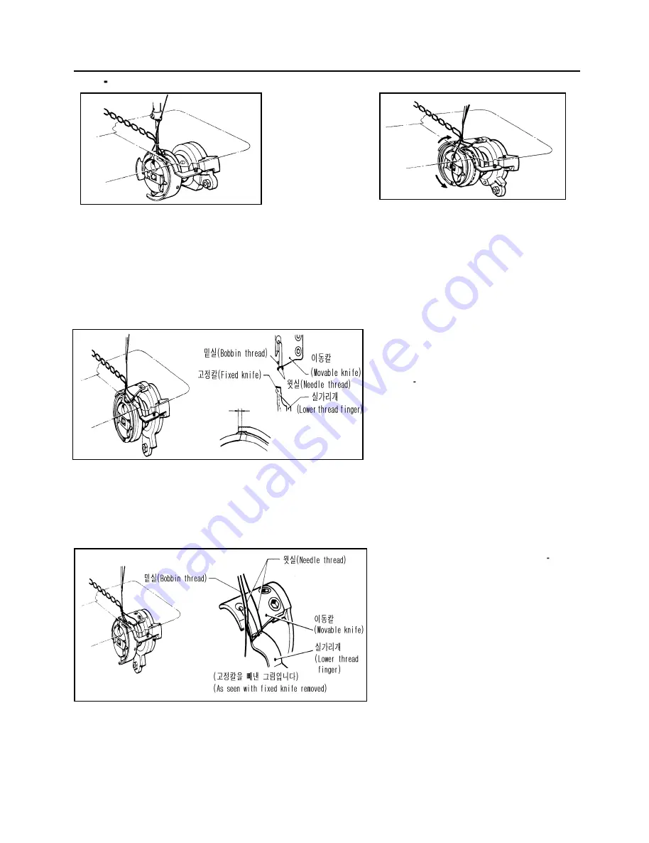
 3. 윗 ․밑실 의 사 절 순서 / Needl e and bobbin thread trimming


 (1) 바늘이 최하점에서 2.0mm일 때, 가마칼끝은 바늘에          (2) 사절신호가 들어가 사절캠에 의해 이동칼이 이동합

    만들어진 루프를 끌어올립니다. (후물사양 2.2mm)             니다. 윗실은 가마에 포착되어 내가마를 빠져나갑니다.

 (1) When the needle rises 2mm(2.2mm with thick materials)     (2) When the thread trimmer signal is turned on, the  

    above its lowest position, the rotary hook point catches        thread trimmer clutch drives the movable knife. The  

    the loop formed by the needle.                            needle thread is caught by the rotary hook and fed  

                                                           around the shuttle body. 


    (3)  이동칼선단은  가마칼끝에  의해  침판하측    

        에서  형성된  삼각루프  안에  들어가서,     

        윗․밑실의  실처리를  합니다.  이때  천평은   

        거의 

최하점에서 

상승한 

위치이고        

        (상축회전각  약330

˚

)  윗실은  이동칼에     

         의해  그림과  같이  분리됩니다.  이상과    

         같이  타이밍이  빨라도  사절칼의  실처리에  

         영향이 나타나 사절미스 등을 발생합니다. 

(3) The movable knife tip enters and spreads the triangular loop formed by the rotary hook point under the needle plate. 

    At this point, the thread take-up is raised slightly above its lowest position(the upper shaft has turned approximately  

    330

˚

), and the needle thread is spread by the movable knife as shown  in the figure above. If the  timing of the     

    movement is too early, the loop will not be spread properly, and the thread may not be trimmed as a result.

      4)  (3)에서  이동칼에  포착된  윗․밑실은     

          부채꼴로  된  칼형상과  실가리개에  의해   

          서서히  넓게되면서  고정칼선단에서  절단  

          됩니다.  이때,  천평은  거의  최상점에      

          있습니다.  이동칼이  실을  넓히고  있을때  

          윗실에  무리한  힘이  발생하지  않도록     

          동시에  실늦추기가 작동해서  윗실 공급을  

          부드럽게 합니다. 

(4) The needle and bobbin threads caught by the movable knife in step(3) are gradually spread by the movable knife    

    and lower thread finger to be cut by the fixed knife tip. At this time, the needle thread take-up approaches the top  

    of its stroke. When the movable knife is spreading the needle thread, the tension release relieves the needle thread  

    tension to prevent excessive tension and to enable the needle thread to be extended smoothly.

All manuals and user guides at all-guides.com

Summary of Contents for LS2-H550

Page 1: ...1 OPERATION MANUAL PART BOOK LS2 H550 LS2 H5500 SINGLE NEEDLE FEED LOCKSTITCH WITH SIDE CUTTER SEWING MACHINE WITH THREAD TRIMMER All manuals and user guides at all guides com a l l g u i d e s c o m...

Page 2: ...All manuals and user guides at all guides com...

Page 3: ...eware of injury This symbol indicates something that you must not do This symbol indicates something that you must do The picture inside the circle indicates the nature of the thing that must be done...

Page 4: ...5 off A S 31 2 40 25 OFF A S A S All manuals and user guides at all guides com...

Page 5: ...overs to the machine head and motor Be sure to wear protective goggles and gloves when handling the lubricating oil and grease so that they do not get into your eyes or onto your skin otherwise inflam...

Page 6: ...not using the machine and when leaving the machine unattended For machines with automatic presser lifter do not touch the solenoid section because if becomes hot during operation and may cause severe...

Page 7: ...y maintenance and inspection of the electrical system Turn off the power switch and disconnect the power cord from the wall outlet at the following times otherwise the machine may operate if the tread...

Page 8: ...N dealer The positions of the labels may vary slightly depending on the model of sewing machine or motor 1 2 Be sure to connect the ground If the ground connection is not secure you run a high risk of...

Page 9: ...rned on verify the rotational direction of the pulley with the power on The pulley should rotate counterclockwise when viewed from the pulley Power must be turned off when the machine is not in use or...

Page 10: ...8 4 Needle feed mechanism 8 5 Feed regulation mechanism 9 6 Thread wiper 9 7 Knife mechanism 10 8 Thread trimmer 11 14 ADJUSTMENT 15 24 1 Adjusting the needle bar height 15 2 Adjusting the rotary hook...

Page 11: ...l the belt V V 13mm 16mm Tilt back the machine head and place the belt onto the motor pulley and machine pulley Press belt with a finger force of 5 N and adjust the nut so that there is a deflection o...

Page 12: ...off any contamination from the magnet and the oil pan Use the oil specified by Spindle15 2 Adjusting lubrication for upper shaft and rotary hook 1 1 Upper shaft lubrication Remove the face plate and...

Page 13: ...e needle plate 2 Upper knife operation To operate the upper knife lower the upper knife set lever The upper knife will now operate in sync with the operation of the machine To stop the upper knife rai...

Page 14: ...needle DB 1 Insert the needle completely making sure that the lengthwise groove of the needle is on the left and secure it using the set screw Use a DBx1 needle 4 Threading the needle All manuals and...

Page 15: ...3 Pull the thread from the bobbin case tension spring 6 Winding the bobbin thread 1 2 3 4 1 Fit the bobbin in the bobbin winder shaft 2 Depress the joint as far as it will go 3 Wind the bobbin thread...

Page 16: ...djust the operation range of the thread take up spring loosen the set screw and turn the thread tension bracket assembly To adjust the tension of the thread take up spring fit a screwdriver into the s...

Page 17: ...mp moves the needle bar vertically 4 The needle bar is guided by the needle bar bracket 2 Lower shaft and rotary hook mechanism 1 2 3 1 When the pulley turns in the direction of the arrow the bevel ge...

Page 18: ...eed rocker shaft and the feed rocker bracket arm 5 When the inclination of the feed regulator and the pivot point of the level feed link change the horizontal momentum of the level feed arm link chang...

Page 19: ...nclination decides the feed amount of the feed rocker mechanism and the needle bar mechanism Pressing the reverse lever reverses the inclination of the feed regulator to feed the material in reverse 1...

Page 20: ...tric wheel with the screw moves vertically at the cam part eccentric part of the thread take up crank assembly 4 The knife driving link the knife driving rod and the knife shaft clamp assembly attache...

Page 21: ...figures show the thread trimmer without the rotary hook assembly 1 During operation The thread trimmer cam lever spring presses the thread trimmer cam lever assembly against the thread trimmer soleno...

Page 22: ...of the thread trimming clutch 3 Movable knife holder action Due to the rotation of the lower shaft the thread trimmer clutch pushes the roller shaft up The motion of the roller shaft is transmitted t...

Page 23: ...he thread trimmer clutch and returns to its original position The thread trimmer lever spring returns the thread trimmer rod and the movable knife holder to their original positions in the direction o...

Page 24: ...tly above its lowest position the upper shaft has turned approximately 330 and the needle thread is spread by the movable knife as shown in the figure above If the timing of the movement is too early...

Page 25: ...h Then firmly tighten the screw A 0 0 5mm 0 0 05mm Align the bottom reference line of the needle bar with surface A of the needle bar oil rejector needle bar bush by turning the machine pulley slowly...

Page 26: ...icated below For thin materials The needle tip is aligned with tips of the feed dog and the upper surface of the needle plate For thick materials There is a 5mm gap between the needle tip and the uppe...

Page 27: ...ew of the needle feed arm then move the needle bar bracket forward or backward 2 Feed dog position Set the feed regulating dial to maximum and turn the machine pulley Check that the needle enters the...

Page 28: ...0Kg 1 Loosen the screw and turn the machine pulley until the needle bar is raised 5 mm above its lowest position then depress the thread trimming solenoid 2 With the thread trimming solenoid depressed...

Page 29: ...thread trimming clutch 3 With the thread trimming solenoid depressed turn the machine pulley Adjust the movable knife and the fixed knife so that they overlap when the rotation of thread trimming clut...

Page 30: ...or down 1 2 2 90 1 When the feed dog is fully raised its angle is properly adjusted if the circle on the feed bracket shaft aligns with the index on the feed rock shaft arm 2 To adjust the feed dog an...

Page 31: ...ed 215 spm 3 Adjust as follows when the forward and backward stitch lengths are different 1 Remove the rear plate 2 Loosen the screw 3 When the forward stitch length is greater than the backward set t...

Page 32: ...ould be a 9 5 11 5 mm gap between the upper surface of the needle plate and the needle tip with thin or medium materials or a 10 12 mm gap with thick materials If adjustment of needle stop position is...

Page 33: ...using the presser bar lifter 2 Remove the screw and the needle plate 3 Remove the screws and the feed dog 4 Remove the screws and the auxiliary needle plate 5 Turn the machine pulley until the needle...

Page 34: ...he back edge pf the upper knife should be aligned with the needle center The upper knife can be adjusted by loosening the screw and moving the knife within a range of 2 mm forward to 3 mm backward 3 U...

Page 35: ...25 4 4 16 15 15 15 4 4 4 6 6 6 2 All manuals and user guides at all guides com...

Page 36: ...igh Thread wiper position Adjust thread wiper position with screw Thread breakage Improper threading Threading Rethread 4 Bent needle Blunt needle tip jammed eye Needle Replace needle 4 Improper needl...

Page 37: ...27 4 4 1 4 4 15 15 15 6 6 All manuals and user guides at all guides com...

Page 38: ...ser bar pressure Tighten presser foot adjustment screw Presser bar height Adjust presser bar height Improper needle to rotary hook timing Needle bar rise Adjust needle to rotary hook timing 15 Needle...

Page 39: ...29 6 6 6 6 puff 15 19 23 4 22 19 23 19 All manuals and user guides at all guides com...

Page 40: ...ap Adjust needle to rotary hook timing 15 Improper thread cutting a Needle bobbin threads not cut b Needle thread not cut c Bobbin thread not cut Movable knife fixed knife do not overlap Adjust knives...

Page 41: ...31 6 1 22 6 24 24 24 24 All manuals and user guides at all guides com a l l g u i d e s c o m...

Page 42: ...transmitted Check circuits refer to motor adjustment manual Thread wiper does not function Needle thread remainder too long Adjust pretension 6 Timing too early wipes thread before tension disc closes...

Page 43: ...33 All manuals and user guides at all guides com...

Reviews: