- 28 -
3. 사절캠 위치 결정 / POSITIONING OF THREAD TRIMMER CAM
☞
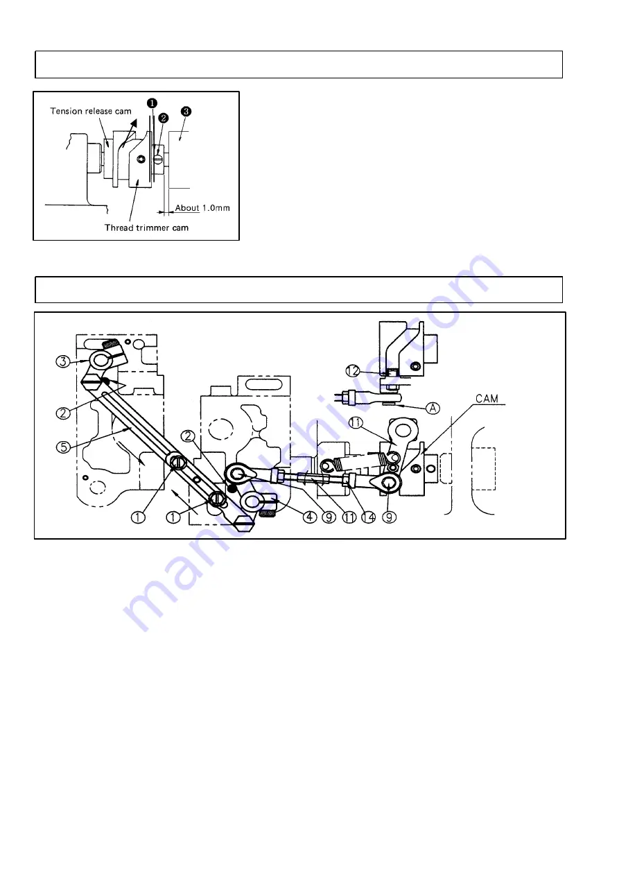
캠 붓싱①면과 하축 붓싱③면 사이를 약 1.0mm 정도로 하여
나사②를 하축나사 자리면에 고정하여 주십시오.
☞
Fix the screw② on the side of the lower shaft screw with
the gap 1.0㎜ between the cam bushing① and the lower
shaft bushing③.
4. 연결로드 길이 조정법 / ADJUSTMENT OF NEEDLE GAUGE DISTANCE
(1) 연결판⑤⑥에 고정된 2개 나사①를 4㎜렌치로 가볍게 늦추어 주십시오.
(2) 연결판⑤⑥을 화살표 방향으로 움직여서 이동칼 레버③④의 가공된 면이 가마대에 고정된 2개의
스톱퍼핀②에 완전히 붙게 나사① 2개로 고정하여 주십시오.
(3) 볼 조인트 베어링⑦⑧에 단나사⑨를 고정하여 주십시오.
(4) 스톱퍼핀②에 이동칼 레버④ 가공면을 완전히 붙게 합니다.
(5) 조절나사⑩를 화살표 방향으로 조절하여 롤러⑫가 CAM 좌측 홈 중앙에서 부드럽게 움직이도록
너트⑬⑭를 고정하여 주십시오.
시계방향 : 길이 증가 반시계 방향 : 길이 감소
(6) 이때
Ⓐ
부를 눌렀을 때 베어링이 캠 홈 속에서 가볍게 복귀운동을 하는지 확인 바랍니다.
(1) Slightly loosen the two screw① fixed at the connected board by the wrench 4㎜.
(2) After the processed side of the driving knife lever③④ absolutely sticks to the two stopper pin②
fixed at the rotary hook, fix the connecting board⑤⑥ moved along the arrow as the two screw①.
(3) Fix the stud screw⑨ at the ball joint bearing ⑦⑧.
(4) Absolutely stick the driving knife lever④ to the stopper pin②.
(5) Adjust the adjusting screw⑩ along the arrow, and when the roller⑫ is moved smoothly at the
groove center of the cam left side, fix the screw⑬⑭.
clockwise : length increase counterclockwise : length decrease
(6) When you push
Ⓐ
, ascertain whether the bearing slightly returns in the cam groove.
Summary of Contents for LT2-H650
Page 2: ...1...
Page 4: ...5 off A S 44 2 40 25 OFF A S A S 3...
Page 8: ...UNICORN A S 1 2 3 7 3 2 1...
Page 32: ...31 p28 p27 p27 p30 p29 p29 p14 p14 p14 1 p18 p17 p17...
Page 34: ...33...


