background image

Care, maintenance and repair

HT-Series | Version 1.01

17

Daily maintenance:

- Check all components for damage and have them 

replaced by qualified personnel if necessary..

Monthly maintenance::

- Slightly lubricate the rollers and bearings.

Yearly maintenance:

- Carry out and document lift table inspection in ac-

cordance with regulations.

- Models HT 600 and HT 600 LAP:                      

Change hydraulic oil

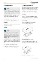
Move the platform slightly upwards to fold in the main-
tenance supports.

If maintenance or repair work has been carried out on 
the lift table, a function check must then be carried out. 

- It is forbidden to access the lift table if it is not se-

cured by the safety support.

- Wear suitable protective clothing.
- Wear safety shoes
- Before working on the hydraulic system, depres-

surise it by lowering the lifting table onto the safety 
supports.

If the lift table is used 

very frequently

 or regularly under 

"

difficult operating condition

s" (e.g. in particularly dusty 

environments, under the influence of chemicals or 
vapours, etc.), the inspection should be carried out at 
shorter intervals.

If you have any questions about the condition of the lift 
table, please contact a specialist workshop.

If the lift table does not function properly, contact a spe-
cialist dealer or our customer service. Contact details 
can be found in chapter 1.2 Customer service.

All protective and safety devices must be reinstalled im-
mediately after completion of repair and maintenance 
work. 

Step 1: Lubricate all moving parts of the lift table with 

high quality grease.

Step 2: Check the lift table for external damage before 

each use.

Step 3: Models HT 600 and HT 600 LAP: Check the hy-

draulic oil level at regular intervals.

Step 4: Make sure that all safety notices on the lift table 

are clearly legible.

Check oil level (only models HT 600 and HT 600 LAP ) /                 
Oil changes

Step 1: Lower the lift table and open the cap on the 

pump tank filler neck. 

For oil change: Drain used oil.

Step 2: Top up oil (HLP 32) if necessary or when 

changing oil. Oil tank volume: 1 litre. 

Oil quantity in the hydraulic cylinder: 
max. 0.66 litres.

Step 3: Close the filler neck and lift and lower the lift 

table several times. Check the oil level again 
and screw in the screw plug again.

Step 4: Bleed the hydraulic system (see "Venting").

Venting (only Models HT 600 and HT 600 LAP)

After some time, or after filling with oil, air bubbles may 
form in the hydraulic system of the lift table and affect its 
function.

Step 1: Lower the lift table to min. height

Step 2: Slowly and carefully open the oil filler plug to 

allow the trapped air to escape.

Step 3: Check the lift table for proper function, repeat if 

necessary.

Oil, grease and cleaning agents are ha-

zardous to the environment and must not 
be added to waste water or normal 
household waste. Dispose of these 
agents in an environmentally friendly 
manner.

NOTE!

The hydraulic cylinders (with integrated pump) of the 
HT 300 series (HT 300 S, HT 300 M and HT 300 L) are 
maintenance-free. If an oil leak occurs, the cylinder 
must be replaced.

NOTE!

HT 600 and HT 600 LAP: The oil level must be chec-
ked by a specialist workshop or specialist at least 
once a year.

WARNUNG!

The cleaning cloths soaked in oil, grease or cleaning 
agents are easily combustible. Collect the rags or 
the cleaning wool in a suitable, closed container and 
dispose of them in an environmentally friendly man-
ner - do not dispose of them with your household 
waste!

Summary of Contents for 6100300

Page 1: ...HT S ERIES HT 300 S Operating instructions Lift Table HT 300 S HT 300 M HT 300 M PSR HT 300 L HT 300 L LAP HT 600 HT 600 LAP HT 300 M PSR HT 600 HT 300 L...

Page 2: ...ymbol explanation 3 2 2 Obligations of the operating company 4 2 3 Requirements to staff 5 2 4 Personal protective equipment 5 2 5 Safety instructions 5 2 6 General safety regulations 6 2 7 Safety reg...

Page 3: ...always interested in valuable experience and knowledge gained from using the application which then could be shared and be valuable to develop our products even further 1 3 Limitation of liability All...

Page 4: ...ssary The operating company must unambiguously reg ulate and determine the responsibilities for instal lation operation troubleshooting maintenance and cleaning The operating company must ensure that...

Page 5: ...ec tive equipment while performing different tasks on and with the machine which are indicated in the individual paragraphs of these instructions The personal protective equipment is explained in the...

Page 6: ...minimum age 18 years who are familiar with these operating instructi ons in particular the safety regulations should be au thorised to do the work All other regulations on work safety and accident pre...

Page 7: ...be ensured that the user can operate the lift table with the load without any problems We point out that in case of improper use no liabi lity for possible consequential damages can be assumed This a...

Page 8: ...on firm level ground in perfect condition and only by instructed persons Intended use also includes compliance with all information in these instructions Any use beyond the intended use or any other u...

Page 9: ...300 300 300 600 600 Table height min mm 400 400 400 400 430 400 430 Table height max mm 1010 1010 1010 1010 1040 1010 1040 Roll diameter mm 125 125 125 125 125 125 125 Max plate weight for swivel fra...

Page 10: ...re recyclable and should be taken to a materials recycling depot to be disposed of The delivery packaging is made of cardboard so please dispose carefully by having it chopped up and given to the recy...

Page 11: ...mp to the hydraulic cylinder Foot pump and hydraulic cylin der are a fixed unit HT 300 M PSR Provides one person with easy loading of panels onto the platform frame and pivoting from vertical to horiz...

Page 12: ...onof the lift table into the existing ma chinery must be carried out in such a way that the basic safety requirements of the EC Machinery Di rective 2006 42 EC are observed must be chec ked by the ope...

Page 13: ...ift table the operator must ensure that there is no danger from the movement of the lift platform DANGER DANGER TO LIFE DUE TO FALLING OF THE LOAD Falling loads can cause serious injury or death Never...

Page 14: ...gainst fal ling by suitable equipments However it is usually not necessary to secure the load It is only necessary for loads that have an unstable position on the lift platform e g rolling elements Lo...

Page 15: ...lers By repeatedly pressing the lever Fig 10 the platform moves upwards Lock the brakes before lifting and lo wering loads Fig 10 Lifting the lift table HT 300 top HT 300 L bottom Fig 10 Lifting the l...

Page 16: ...ance or repair work has been carried out on the lift table a function test must then be carried out It is forbidden to reach into the lift if it is not secu red by the maintenance support Wear suitabl...

Page 17: ...odels HT 600 and HT 600 LAP Check the hy draulic oil level at regular intervals Step 4 Make sure that all safety notices on the lift table are clearly legible Check oil level only models HT 600 and HT...

Page 18: ...condition of the compo nents and equipment the completeness and effective ness of the safety equipment and the completeness of the test book If a test period of no more than one year is adhered to the...

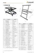
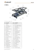
Page 19: ...ring spare parts send a copy of the spare parts drawing with the marked component guide roll and marked item number 13 to the authorised dealer or to the spare parts department and provide the followi...

Page 20: ...lever 8 1 19 001 060 02 Foot bar 4 3 DIN 125 A17 Washer 8 2 19 001 060 03 Fastening 4 4 DIN 625 T1 6203 2RS Deep groove ball bearing 8 3 DIN 913 MS x 20 Threaded pin 4 5 ISO 10511 M16 Hex nut 8 4 ISO...

Page 21: ...4032 M8 Threaded pin 6 5 ISO 4014 M16 x110 Hex bolt 3 5 ISO 4762 M8 x 45 Allen screw 6 6 ISO 4014 M16 x 65 Hex bolt 4 19 020 011 00 AA Base frame 7 19 020 041 00 AA Support frame 5 19 020 020 00 AA S...

Page 22: ...AA Support frame 8 19 020 051 00 AA Pressure fork 10 ISO 4017 M8 x 10 Hex nut 9 ISO 4017 M12 x 30 Hex nut 11 ISO 4762 M8 x12 Allen screw 12 DSCO101 12 82 Medipack 13 L IL PUZK 125 K 3 Guide roll 14 L...

Page 23: ...Scissors large cpl 9 Wheel base cpl 4 1 Bolt 9 1 Rectangular tube 4 2 Scissors large 9 2 Hex bolt 4 3 Washer 9 3 Tube cover 90x40x4 4 4 Lock ring 9 4 Guide roll 4 5 Groove ball bearing 10 Base frame c...

Page 24: ...ors small 4 10 DIN 471 25 x1 2 Locking ring 3 5 DIN1850 G 22x32 x20 Bearing 4 11 DIN 471 28 x 1 5 1 Locking ring 3 6 DIN 1850 G 28x32 x30 Bearing 4 12 DIN 625 T1 6304 2RS Groove ball bearing 3 7 DIN 4...

Page 25: ...to the information on the type plate complies with the relevant fundamental safety and health requirements of the above mentioned EC Directive and the other directives applied hereinafter including th...

Page 26: ...www unicraft de...
Reviews: