background image

Technical Data

PG-E-Series | Version 2.08

7

4

Technical Data

4.1 Table 

Model

PG-E 30 
SRA

PG-E 40 
SRA

Voltage

230 V

230 V

Emergency output 
LTP

2,8 kW

3,8 kW

Continuous output 
COP

2,5 kW

3,3 kW

Fuel

Petrol

Petrol 

Starter

Manual 
start

Manual 
start

Running time 
at 50% load

12,5 hours

14 hours

Running time 
at 100% load

9,5 hours

9,5 hours

Tank capacity

15 Liter

15 Liter

Sound pressure level

75 dB(A)

75 dB(A)

Weighted sound 
power level (L

WA

)

95 dB(A)

95 dB(A)

Socket type

2x 230V 
shockproof 

2x 230V 
shockproof 

Generator IP degree 
of protection 

IP 23

IP 23

Socket IP degree of 
protection 

IP 44

IP 44

Dimensions (LxWxH)  
[mm]

595x460x
500 

595x460x
527 

Weight

45 kg

50 kg

Motor oil volume
min./max.

0,25 - 0,6     
liter

0,25 - 0,6       
liter

Model

PG-E 60 
SEA

PG-E 80 TEA

Voltage

230 V

230V/400 V

Emergency output 
LTP 230V

5,5 kW

2,5 kW

Continuous output 
COP 230V

5,0 kW

2,3 kW

Emergency output 
LTP 400V


7,0 kW

Continuous output 
COP 400V


6,5 kW

Fuel

Petrol 

Petrol 

Starter

Manual 
start

Manual start/
Electric starter

Running time 
at 50% load

16 hours

13 hours

Running time 
at 100% load

8,2 hours

8,5 hours

Tank capacity

25 Liter

25 Liter

Sound pressure       
level

76 dB(A)

76 dB(A)

Weighted sound 
power level (L

WA

)

96 dB(A)

96 dB(A)

Socket type

2x 230 V 
shockproof/
1x 230V 
CEE 32A

2x 230 V 
shockproof/
1x 400V CEE 
16A

Generator IP degree 
of protection 

IP 23

IP 23

Socket IP degree of 
protection 

IP 44

IP 44

Dimensions 
(LxWxH)  [mm]

700x526x
580

700x526x
580 

Weight

81 kg

88 kg

Motorö oil volume 
min./max.

0,55 - 1,1   
liter

0,6 - 1,2 
liter

Summary of Contents for 6706030

Page 1: ...PG E S ERIES PG E 80 TEA Operating Instructions Generator PG E 30 SRA PG E 40 SRA PG E 60 SEA PG E 90 SEA PG E 80 TEA PG E 100 TEA ...

Page 2: ...ns and error Content 1 Introduction 3 1 1 Copyright 3 1 2 Customer service 3 1 3 Limitation of liability 3 2 Safety 3 2 1 Symbol explanation 3 2 2 Obligations of the operating company 4 2 3 Requirements to staff 4 2 4 Personal protective equipment 5 2 5 General safety regulations 5 2 6 Safety labels on the generator 6 2 7 Safety data sheets 6 3 Intended Use 6 4 Technical Data 7 4 1 Table 7 4 2 Typ...

Page 3: ...g the application which then could be shared and be valuable to develop our products even further 1 3 Limitation of liability All information and notes in these operating instructions were summarised while taking applicable standards and rules the state of the art technology and our long term knowledge and experiences into consideration In the following cases the manufacturer is not liable for dam...

Page 4: ... intervals and inform them about the dan gers The operator must provide the personnel with the necessary protective equipment and instruct them to wear the required protective equipment in a bin ding manner Furthermore the operator is responsible for ensuring that the machine is always in perfect technical condition The following therefore applies The operator must ensure that the maintenance in t...

Page 5: ...ting and levelling de vices to ensure safe stand the generator If the generator is to be used in rain or snow provide adequate protection and stability Keep children away from the running generator at all times and in any case ensure that the motor re mains hot for about one hour when switched off The exhaust pipes exhaust pipes and motor are the areas where the elevated temperatures last the lon ...

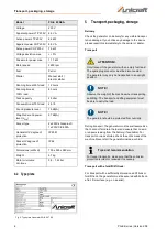
Page 6: ...tached 2 7 Safety data sheets You can obtain safety data sheets for dangerous goods from your specialist dealer or by calling 49 0 951 96555 0 Specialist dealers can find safety data sheets in the download area of the partner portal 3 Intended Use The generator is used exclusively to generate electricity The generator can be used universally for 230V and 400V only model PG E 80 TEA The generator m...

Page 7: ...ht 45 kg 50 kg Motor oil volume min max 0 25 0 6 liter 0 25 0 6 liter Model PG E 60 SEA PG E 80 TEA Voltage 230 V 230V 400 V Emergency output LTP 230V 5 5 kW 2 5 kW Continuous output COP 230V 5 0 kW 2 3 kW Emergency output LTP 400V 7 0 kW Continuous output COP 400V 6 5 kW Fuel Petrol Petrol Starter Manual start Manual start Electric starter Running time at 50 load 16 hours 13 hours Running time at...

Page 8: ...8 2 kW Apparent power COP 230V 8 0 VA Active power COP 230V 7 5 kW Voltage deviation max 3 Drive motor power max 11 7 kW Motor speed 3600 rpm Fuel Petrol Starter Manual start Electric starter Running time at 50 load 12 hours Running time at 100 load 8 hours Tank capacity 25 Liter Consumption at 75 load 2 5 l h Sound pressure level 75 dB A Weighted sound power level LWA 97 dB A Socket type 2x 230V ...

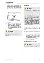
Page 9: ...ill warm drain oil from crank case Refill with recommended grade Fig 3 Drain oil and petrol Step 3 Remove spark plugs and pour about 1 2 ounce 15 ml of motor oil the cylinders Cover spark plug hole with rag Pull the recoil starter a couple times to lubricate the piston rings and cylinder bore Step 4 Install and tighten spark plugs Do not connect spark plug wires Step 5 Clean the generator outer su...

Page 10: ...indicator 7 Petrol tank 8 Choke 9 Spark plug 10 Silencer 11 Starter 12 Air filter 13 Ground terminal 14 ONN OFF switch Motor START switch Fig 5 Control panel PG E 40 SRA top and PG E 80 TEA down 1 ONN OFF switch Motor START switch 2 Display voltage frequency operating hours 3 Fuse switch 4 Oil control lamp 5 Ground connection 6 230 V Consumer socket 7 230 V Consumer socket 8 400 V Consumer socket ...

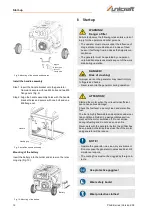
Page 11: ...e bottom of the bum per bracket Secure the bolt with an M8 flange nut Fig 7 Mounting of the wheels and bumpers Mounting the wheels on PG E 90 SEA Step 1 Slide the axle through the frame brackets Step 1 Slide the axle through the frame brackets Step 2 Slide on the hub wheel and flat washer Step 3 Insert the cotter pin through the wheel axle hole Step 4 Bend the cotter pin tabs outward to lock the p...

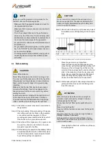
Page 12: ...om an illness that impairs con centration The generator must be operated by one person only Additional persons must keep out of the work area during operation DANGER Risk of crushing Improper work on the generator may result in injury to fingers and hands Never reach into the generator during operation ATTENTION Starting the motor when the oil level is insufficient can cause serious damage Check t...

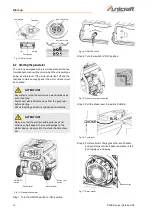
Page 13: ...er is connected to the generator The oil has a large influence on the performance and service life of the motor The motor s Operation and Maintenance Manual lists the characteristics of the oil and the ideal oil level for this generator For petrol motor versions the cold start choke must be switched on For generators with electric ignition turn the ignition key to the START position and release it...

Page 14: ...he choke lever to position CHOKE Fig 16 Choke lever Step 4 For Recoil start firmly grasp the recoil handle and pull slowly until increased resistance is felt Pull rapidly up and away Fig 17 Recoil starter ATTENTION Never start or stop the motor when electrical devices are connected Disconnect all electrical devices from the generator before starting Check that the generator is positioned horizonta...

Page 15: ...ator or circuit breaker rating of the receptacle supplying the power Step 3 Plug in the electrical consumer s The consu mers must be switched off Step 4 Switch on the electrical consumer s ATTENTION If motor fails to start after 3 pulls or if unit shut down during operation make sure unit is on a level sur face and check for proper oil level in crankcase Low oil shut off ATTENTION Do not connect e...

Page 16: ...el is used up and the generator stops Cover the cooled generator and protect it from moisture See chapter Storage for further measures ATTENTION After the motor has been switched off it still emits heat so sufficient ventilation should be provided even after the generator has been switched off ATTENTION All cleaning care maintenance and repair work may only be carried out with the generator switch...

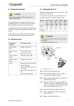
Page 17: ...wly pour the new oil through the oil filter into the motor until the level reaches the mark on the dipstick In the meantime check the level several times Never exceed the max level Step 5 Close the filling opening tightly with the cap Step 6 Wipe up spilled oil Check the oil level before each motor start Step 7 Dispose of the used oil properly CAUTION Maintenance and repair works must only be per ...

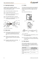
Page 18: ...the spark arrestor screen with a small wire brush Step 3 Replace the spark arrestor if it is damaged In stall the Spark arrestor reversely 9 7 Air filter The motor will not run properly and may be damaged if using a dirty air filter Replace the air filter once a year Clean or replace more often if operating under dusty conditions Step 1 Remove the air filter cover Fig 21 Cleaning air filter Step 2...

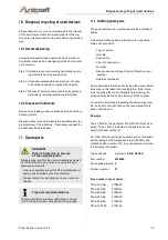
Page 19: ... air express Address of dispatch Spare part orders which do not include the above indica tions may not be taken into consideration If the indica tions regarding the mode of dispatch are missing the product is dispatched at the discretion of the supplier You will find information regarding the device type item No and year of construction on the type plate which is fixed on the device Example The ai...

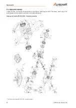
Page 20: ...vice the following drawing shall help to identify the necessary spare parts If necessary send a copy of the parts drawing with the marked components to your authorised dealer Spare parts drawing PG E 30 SRA Complete assembly Fig 22 Spare parts drawing PG E 30 SRA complete assembly ...

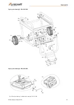
Page 21: ...Spare parts PG E Series Version 2 08 21 Spare parts drawing 1 PG E 30 SRA Fig 23 Spare parts drawing 2 and Spare parts drawing 2 PG E 30 SRA Spare parts drawing 2 PG E 30 SRA ...

Page 22: ...22 PG E Series Version 2 08 Spare parts Spare parts drawing 3 PG E 30 SRA Fig 24 Spare parts drawing 3 PG E 30 SRA ...

Page 23: ...Spare parts PG E Series Version 2 08 23 Spare parts drawing 4 PG E 30 SRA Fig 25 Spare parts drawing 4 PG E 30 SRA ...

Page 24: ...24 PG E Series Version 2 08 Spare parts Spare parts drawing 5 PG E 30 SRA Fig 26 Spare parts drawing 5 PG E 30 SRA ...

Page 25: ...Spare parts PG E Series Version 2 08 25 Spare parts drawing PG E 40 SRA complete assembly Fig 27 Spare parts drawing PG E 40 SRA ...

Page 26: ...26 PG E Series Version 2 08 Spare parts Spare parts drawing 1 PG E 40 SRA Fig 28 Spare parts drawing 1 and Spare parts drawing 2 PG E 40 SRA Spare parts drawing 2 PG E 40 SRA ...

Page 27: ...Spare parts PG E Series Version 2 08 27 Spare parts drawing 3 PG E 40 SRA Fig 29 Spare parts drawing 3 PG E 40 SRA ...

Page 28: ...28 PG E Series Version 2 08 Spare parts Spare parts drawing 4 PG E 40 SRA Fig 30 Spare parts drawing 4 PG E 40 SRA ...

Page 29: ...Spare parts PG E Series Version 2 08 29 Spare parts drawing 5 PG E 40 SRA Fig 31 Spare parts drawing 5 PG E 40 SRA ...

Page 30: ...30 PG E Series Version 2 08 Spare parts Spare parts drawing PG E 60 SEA PG E 80 TEA and PG E 90 SEA Complete assembly Fig 32 Spare parts drawing PG E 60 SEA PG E 80 TEA and PG E 90 SEA complete assembly ...

Page 31: ...ion 2 08 31 Spare parts drawing 1 PG E 60 SEA PG E 80 TEA and PG E 90 SEA Fig 33 Spare parts drawing 1 und Spare parts drawing 2 PG E 60 SEA PG E 80 TEA and PG E 90 SEA Spare parts drawing 2 PG E 60 SEA PG E 80 TEA and PG E 90 SEA ...

Page 32: ...32 PG E Series Version 2 08 Spare parts Spare parts drawing 3 PG E 60 SEA PG E 80 TEA and PG E 90 SEA Fig 34 Spare parts drawing 3 PG E 60 SEA PG E 80 TEA and PG E 90 SEA ...

Page 33: ...Spare parts PG E Series Version 2 08 33 Spare parts drawing 4 PG E 60 SEA PG E 80 TEA and PG E 90 SEA Fig 35 Spare parts drawing 4 PG E 60 SEA PG E 80 TEA and PG E 90 SEA ...

Page 34: ...34 PG E Series Version 2 08 Spare parts Spare parts drawing 5 PG E 60 SEA PG E 80 TEA and PG E 90 SEA Fig 36 Spare parts drawing 5 PG E 60 SEA PG E 80 TEA and PG E 90 SEA ...

Page 35: ...Spare parts PG E Series Version 2 08 35 Spare parts drawing 1 PG E 100 TEA Complete assembly Fig 37 Spare parts drawing 1 PG E 100 TEA Complete assembly ...

Page 36: ...36 PG E Series Version 2 08 Spare parts Spare parts drawing 2 PG E 100 TEA Fig 38 Spare parts drawing 2 PG E 100 TEA ...

Page 37: ...Spare parts PG E Series Version 2 08 37 Spare parts drawing 3 PG E 100 TEA Fig 39 Spare parts drawing 3 PG E 100 TEA ...

Page 38: ...38 PG E Series Version 2 08 Spare parts Spare parts drawing 4 PG E 100 TEA Fig 40 Spare parts drawing 4 PG E 100 TEA ...

Page 39: ...Spare parts PG E Series Version 2 08 39 Spare parts drawing 5 PG E 100 TEA Fig 41 Spare parts drawing 5 PG E 100 TEA ...

Page 40: ...40 PG E Series Version 2 08 Electrical Circuit Diagrams 12 Electrical Circuit Diagrams Fig 42 Electrical circuit diagrams PG E 30 SRA above and PG E 40 SRA below ...

Page 41: ...Electrical Circuit Diagrams PG E Series Version 2 08 41 Fig 43 Electrical circuit diagrams PG E 60 SEA above and PG E 80 TEA below ...

Page 42: ...42 PG E Series Version 2 08 Electrical Circuit Diagrams Abb 44 Electrical circuit diagram PG E 90 SEA ...

Page 43: ...Electrical Circuit Diagrams PG E Series Version 2 08 43 Fig 45 Electrical circuit diagram PG E 100 TEA ...

Page 44: ... the other applied directives below including their applicable modifications at the time of the declaration Relevant EU Directives 2014 30 EU EMC directive 2012 19 EU WEEE directive 2000 14 EG Outdoor directive The following harmonized standards have been applied DIN EN ISO 8528 13 2017 03 Reciprocating internal combustion engine driven alternating current generating sets Part 13 Safety ISO 8528 1...

Page 45: ...Notes PG E Series Version 2 08 45 14 Notes ...

Page 46: ...www unicraft de ...

Reviews: