background image

16

PG-E-Series | Version 2.08

Care, maintenance and repair

8.4 Switching off the generator

Step 1: Disconnect or interrupt all electricity consumers 

supplied by the generator. 

Step 2: Disconnect the mains plug(s) of the electrical 

loads from the generator. 

Step 3: Let the motor run unloaded for 2-3 minutes and 

then switch off directly on the motor by actuating 
the switch-off device. This guarantees good coo-
ling.  

 For generators with electric start, set the starter 
switch to "OFF".

Step 4: Close the fuel tap. 

9

Care, maintenance and repair

9.1 Care by cleaning

The generator must always be kept in a clean condition.

All plastic parts and painted surfaces should be cleaned 
with a soft, damp cloth and some neutral cleaner.  

Remove excess grease or leaked oil with a dry, lint-free 
cloth.

Always keep the cooling fins clean and free.

ATTENTION!

The generator should be started at least once every 
seven days and be allowed to run at least 30 minu-
tes. If this cannot be done and the unit must be sto-
red for more than 30 days, use the following 
information as a guide to prepare it for storage.

-  Empty the fuel tank, start the generator and let it run 

until all fuel is used up and the generator stops.

-  Cover the cooled generator and protect it from 

moisture. 

-  See chapter "Storage" for further measures

ATTENTION!

After the motor has been switched off, it still emits 
heat, so sufficient ventilation should be provided 
even after the generator has been switched off.

ATTENTION!

-  All cleaning, care, maintenance and repair work 

may only be carried out with the generator switched 
off.

-  Always disconnect the spark plug connector from 

the spark plug.

-  No electricity consumer may be connected to the 

generator. 

-  Wait until the hot parts have cooled down.

-  Never clean the machine with a water jet or flam-

mable products!

-  Before putting the generator back into operation, 

make sure that it is completely dry.

NOTE!

The warranty does not cover parts of the generator 
that have been misused or negligently handled by 
the operator. For full warranty coverage, the opera-
tor must operate the generator as described in the 
manual. 

Regular adjustments must be made to ensure pro-
per operation of the generator. Follow the instructi-
ons in the "Maintenance schedule"

ATTENTION!

Never use strong cleaning agents to clean of the pla-
stic parts or painted surfaces.  The surface may be 
loosened and consequential damage may occur.

Use protective gloves!

NOTE!

Never use strong cleaning agents for any cleaning-
work. This can damage or destroy the device

Summary of Contents for PG-E Series

Page 1: ...PG E S ERIES PG E 80 TEA Operating Instructions Generator PG E 30 SRA PG E 40 SRA PG E 60 SEA PG E 90 SEA PG E 80 TEA PG E 100 TEA...

Page 2: ...s and error Content 1 Introduction 3 1 1 Copyright 3 1 2 Customer service 3 1 3 Limitation of liability 3 2 Safety 3 2 1 Symbol explanation 3 2 2 Obligations of the operating company 4 2 3 Requirement...

Page 3: ...the application which then could be shared and be valuable to develop our products even further 1 3 Limitation of liability All information and notes in these operating instructions were summarised w...

Page 4: ...intervals and inform them about the dan gers The operator must provide the personnel with the necessary protective equipment and instruct them to wear the required protective equipment in a bin ding m...

Page 5: ...ing and levelling de vices to ensure safe stand the generator If the generator is to be used in rain or snow provide adequate protection and stability Keep children away from the running generator at...

Page 6: ...ached 2 7 Safety data sheets You can obtain safety data sheets for dangerous goods from your specialist dealer or by calling 49 0 951 96555 0 Specialist dealers can find safety data sheets in the down...

Page 7: ...ht 45 kg 50 kg Motor oil volume min max 0 25 0 6 liter 0 25 0 6 liter Model PG E 60 SEA PG E 80 TEA Voltage 230 V 230V 400 V Emergency output LTP 230V 5 5 kW 2 5 kW Continuous output COP 230V 5 0 kW 2...

Page 8: ...2 kW Apparent power COP 230V 8 0 VA Active power COP 230V 7 5 kW Voltage deviation max 3 Drive motor power max 11 7 kW Motor speed 3600 rpm Fuel Petrol Starter Manual start Electric starter Running t...

Page 9: ...ll warm drain oil from crank case Refill with recommended grade Fig 3 Drain oil and petrol Step 3 Remove spark plugs and pour about 1 2 ounce 15 ml of motor oil the cylinders Cover spark plug hole wit...

Page 10: ...ndicator 7 Petrol tank 8 Choke 9 Spark plug 10 Silencer 11 Starter 12 Air filter 13 Ground terminal 14 ONN OFF switch Motor START switch Fig 5 Control panel PG E 40 SRA top and PG E 80 TEA down 1 ONN...

Page 11: ...bottom of the bum per bracket Secure the bolt with an M8 flange nut Fig 7 Mounting of the wheels and bumpers Mounting the wheels on PG E 90 SEA Step 1 Slide the axle through the frame brackets Step 1...

Page 12: ...m an illness that impairs con centration The generator must be operated by one person only Additional persons must keep out of the work area during operation DANGER Risk of crushing Improper work on t...

Page 13: ...r is connected to the generator The oil has a large influence on the performance and service life of the motor The motor s Operation and Maintenance Manual lists the characteristics of the oil and the...

Page 14: ...e choke lever to position CHOKE Fig 16 Choke lever Step 4 For Recoil start firmly grasp the recoil handle and pull slowly until increased resistance is felt Pull rapidly up and away Fig 17 Recoil star...

Page 15: ...tor or circuit breaker rating of the receptacle supplying the power Step 3 Plug in the electrical consumer s The consu mers must be switched off Step 4 Switch on the electrical consumer s ATTENTION If...

Page 16: ...l is used up and the generator stops Cover the cooled generator and protect it from moisture See chapter Storage for further measures ATTENTION After the motor has been switched off it still emits hea...

Page 17: ...ly pour the new oil through the oil filter into the motor until the level reaches the mark on the dipstick In the meantime check the level several times Never exceed the max level Step 5 Close the fil...

Page 18: ...he spark arrestor screen with a small wire brush Step 3 Replace the spark arrestor if it is damaged In stall the Spark arrestor reversely 9 7 Air filter The motor will not run properly and may be dama...

Page 19: ...air express Address of dispatch Spare part orders which do not include the above indica tions may not be taken into consideration If the indica tions regarding the mode of dispatch are missing the pro...

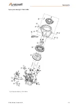
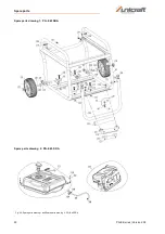
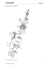
Page 20: ...ice the following drawing shall help to identify the necessary spare parts If necessary send a copy of the parts drawing with the marked components to your authorised dealer Spare parts drawing PG E 3...

Page 21: ...Spare parts PG E Series Version 2 08 21 Spare parts drawing 1 PG E 30 SRA Fig 23 Spare parts drawing 2 and Spare parts drawing 2 PG E 30 SRA Spare parts drawing 2 PG E 30 SRA...

Page 22: ...22 PG E Series Version 2 08 Spare parts Spare parts drawing 3 PG E 30 SRA Fig 24 Spare parts drawing 3 PG E 30 SRA...

Page 23: ...Spare parts PG E Series Version 2 08 23 Spare parts drawing 4 PG E 30 SRA Fig 25 Spare parts drawing 4 PG E 30 SRA...

Page 24: ...24 PG E Series Version 2 08 Spare parts Spare parts drawing 5 PG E 30 SRA Fig 26 Spare parts drawing 5 PG E 30 SRA...

Page 25: ...Spare parts PG E Series Version 2 08 25 Spare parts drawing PG E 40 SRA complete assembly Fig 27 Spare parts drawing PG E 40 SRA...

Page 26: ...26 PG E Series Version 2 08 Spare parts Spare parts drawing 1 PG E 40 SRA Fig 28 Spare parts drawing 1 and Spare parts drawing 2 PG E 40 SRA Spare parts drawing 2 PG E 40 SRA...

Page 27: ...Spare parts PG E Series Version 2 08 27 Spare parts drawing 3 PG E 40 SRA Fig 29 Spare parts drawing 3 PG E 40 SRA...

Page 28: ...28 PG E Series Version 2 08 Spare parts Spare parts drawing 4 PG E 40 SRA Fig 30 Spare parts drawing 4 PG E 40 SRA...

Page 29: ...Spare parts PG E Series Version 2 08 29 Spare parts drawing 5 PG E 40 SRA Fig 31 Spare parts drawing 5 PG E 40 SRA...

Page 30: ...0 PG E Series Version 2 08 Spare parts Spare parts drawing PG E 60 SEA PG E 80 TEA and PG E 90 SEA Complete assembly Fig 32 Spare parts drawing PG E 60 SEA PG E 80 TEA and PG E 90 SEA complete assembl...

Page 31: ...on 2 08 31 Spare parts drawing 1 PG E 60 SEA PG E 80 TEA and PG E 90 SEA Fig 33 Spare parts drawing 1 und Spare parts drawing 2 PG E 60 SEA PG E 80 TEA and PG E 90 SEA Spare parts drawing 2 PG E 60 SE...

Page 32: ...32 PG E Series Version 2 08 Spare parts Spare parts drawing 3 PG E 60 SEA PG E 80 TEA and PG E 90 SEA Fig 34 Spare parts drawing 3 PG E 60 SEA PG E 80 TEA and PG E 90 SEA...

Page 33: ...Spare parts PG E Series Version 2 08 33 Spare parts drawing 4 PG E 60 SEA PG E 80 TEA and PG E 90 SEA Fig 35 Spare parts drawing 4 PG E 60 SEA PG E 80 TEA and PG E 90 SEA...

Page 34: ...34 PG E Series Version 2 08 Spare parts Spare parts drawing 5 PG E 60 SEA PG E 80 TEA and PG E 90 SEA Fig 36 Spare parts drawing 5 PG E 60 SEA PG E 80 TEA and PG E 90 SEA...

Page 35: ...Spare parts PG E Series Version 2 08 35 Spare parts drawing 1 PG E 100 TEA Complete assembly Fig 37 Spare parts drawing 1 PG E 100 TEA Complete assembly...

Page 36: ...36 PG E Series Version 2 08 Spare parts Spare parts drawing 2 PG E 100 TEA Fig 38 Spare parts drawing 2 PG E 100 TEA...

Page 37: ...Spare parts PG E Series Version 2 08 37 Spare parts drawing 3 PG E 100 TEA Fig 39 Spare parts drawing 3 PG E 100 TEA...

Page 38: ...38 PG E Series Version 2 08 Spare parts Spare parts drawing 4 PG E 100 TEA Fig 40 Spare parts drawing 4 PG E 100 TEA...

Page 39: ...Spare parts PG E Series Version 2 08 39 Spare parts drawing 5 PG E 100 TEA Fig 41 Spare parts drawing 5 PG E 100 TEA...

Page 40: ...40 PG E Series Version 2 08 Electrical Circuit Diagrams 12 Electrical Circuit Diagrams Fig 42 Electrical circuit diagrams PG E 30 SRA above and PG E 40 SRA below...

Page 41: ...Electrical Circuit Diagrams PG E Series Version 2 08 41 Fig 43 Electrical circuit diagrams PG E 60 SEA above and PG E 80 TEA below...

Page 42: ...42 PG E Series Version 2 08 Electrical Circuit Diagrams Abb 44 Electrical circuit diagram PG E 90 SEA...

Page 43: ...Electrical Circuit Diagrams PG E Series Version 2 08 43 Fig 45 Electrical circuit diagram PG E 100 TEA...

Page 44: ...the other applied directives below including their applicable modifications at the time of the declaration Relevant EU Directives 2014 30 EU EMC directive 2012 19 EU WEEE directive 2000 14 EG Outdoor...

Page 45: ...Notes PG E Series Version 2 08 45 14 Notes...

Page 46: ...www unicraft de...

Reviews: