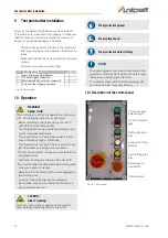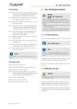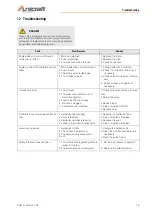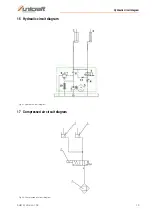
Hydraulic and electrical connection
SHB 3 | Version 1.02
11
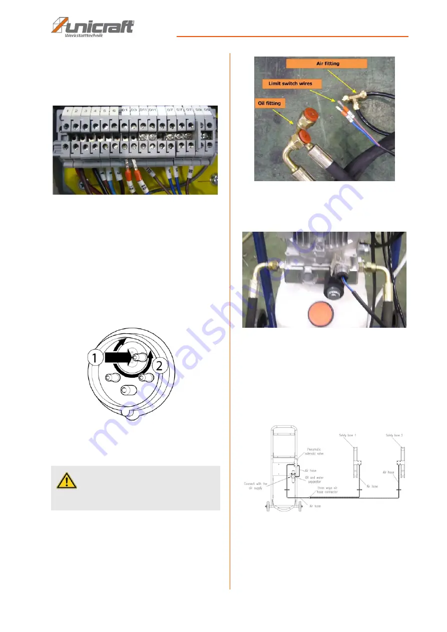
Step 1: Connect the limit switch wiring inside the electri-
cal box as shown in Figure 10.
01 Wiring to 01 Terminal
03 Wiring to 03 Terminal
Fig. 10: Electrical connection
Step 2: Connect the lift to the power supply.
Check motor rotation direction
After electrical connection, check that the direction of
rotation of the motor is correct. If the direction of rotation
is wrong, the connections of the phase lines must be re-
placed.
If equipped with a phase inverter:
Press the disc in the plug with a screwdriver and turn it
by 180°.
Fig. 11: Change motor direction of rotation
8.2 Hydraulic connection
Step 1: Prepare the wires and cables for the lift connec-
tions (Fig.12).
Fig. 12: Hydraulic connection
Step 2: Connect the hydraulic line to the hydraulic
pump. The hoses can be arranged freely on
each side.
Fig. 13: Connection to the hydraulic pump
Step 3: Connect the compressed air (the air pressure
range is between 1.0 and 1.5 kg/cm2 ) to the air
connection of the oil-water separator of the
pump station.
Step 4: Then connect the safety valve to the air outlet of
the pneumatic solenoid valve of the pumping
station.
Fig. 14: Compressed air connection
Step 5: Fill the oil tank with hydraulic oil The distance
between the oil level and the upper edge of the
oil tank should be in the range of 10 to 30 mm.
(Measurement with dipstick on the tank cap)
DANGER!
All work on the hydraulic installation may only be car-
ried out by a qualified person.


