background image

Description

SHB 3 | Version 1.02

9

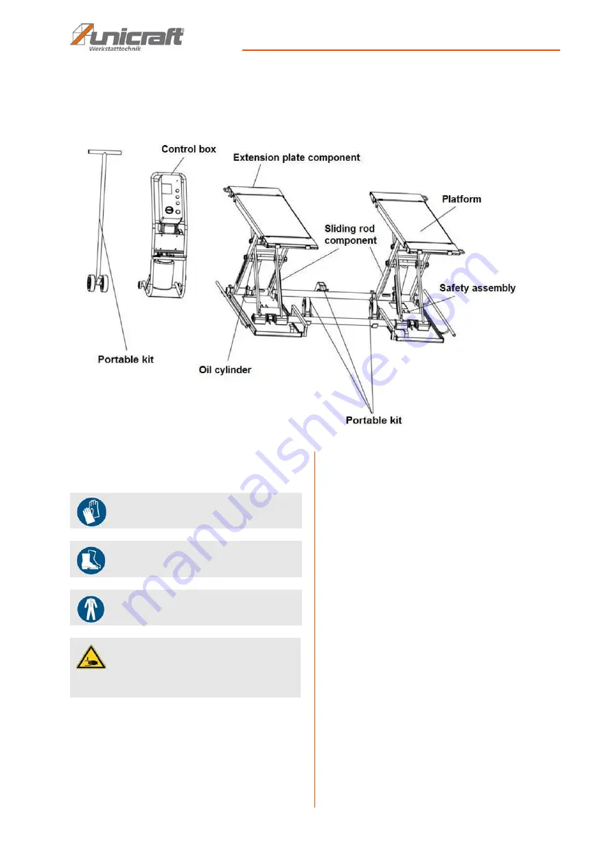
6 Description 

Illustrations in this operating manual may differ from the original.


Fig. 6: Description  

7 Assembly

The following tools are required for assembly: 

- Electric drill
- Wrench
- Screwdriver
- Hammer
- Spirit level

7.1 Requirements for the installation site

The lifting platform must be set up on a level and solid 
base. It must be ensured that there is sufficient freedom 
of movement for working. The installation site should 
meet the following criteria:

- The substrate must be level, solid and vibration-

free with a compressive strength of more than 3kg /
mm², a difference in level of less than 5 mm and a 
minimum thickness of 200 mm (Fig.7). This thick-
ness is required for fixing with the ground anchors.  

- The substrate must not allow lubricants to pass th-

rough. 

- The installation or working area must be dry and 

well ventilated.

- There must be sufficient space for the operating 

personnel, for adjustment and maintenance work.

- The installation site must have good lighting.
- A new concrete floor must be dry for at least 28 

days before the lift can be installed. 

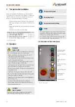
Use protective gloves!

Use protective boots!

Use Protective clothes!

CAUTION!
Risk of crushing!

There is a risk of injury to upper limbs when working 
improperly on the scissor lift.

Summary of Contents for SHB 3

Page 1: ...SHB 3 SHB 3 Instruction Manual Scissor lift SHB 3...

Page 2: ...eb hne 5 2 6 Warnhinweise an der Hebeb hne 6 2 7 Allgemeine Sicherheitsvorschriften 7 2 8 Sicherheitsvorrichtungen 7 3 Bestimmungsgem e Verwendung 8 3 1 Vorhersehbarer Fehlgebrauch 8 3 2 Restrisiken 8...

Page 3: ...om using the application which then could be shared and be valuable to develop our products even further 1 3 Limitation of Liability All information and notes in these operating instructions were summ...

Page 4: ...ed by her correspond to the current status of the regulations and must adapt these if necessary The operating company must unambiguously reg ulate and determine the responsibilities for instal lation...

Page 5: ...ent serves to protect per sons against impairments of safety and health while wor king The staff member has to wear personal protective equipment while performing different tasks on and with the machi...

Page 6: ...6 SHB 3 Version 1 02 Safety 2 6 Warnings on the lifting platform Warnings are attached to the lifting platform Fig 2 which must be observed and followed Fig 2 Warnings on the lifting platform...

Page 7: ...the vehicle that could cause excessive weight shift Make sure that all safety precautions are in place before working near or under the vehicle Never re move safety relevant components from the lift D...

Page 8: ...packaging aids used are recyclable and must always be sent for material recy cling Shredded cardboard packaging components should be sent to the waste paper collection The films are made of polyethyle...

Page 9: ...ion free with a compressive strength of more than 3kg mm a difference in level of less than 5 mm and a minimum thickness of 200 mm Fig 7 This thick ness is required for fixing with the ground anchors...

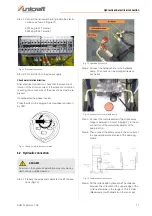
Page 10: ...properly groun ded socket Lay the power cable so that it does not interfere with work and cannot be damaged Protect the power cord from heat aggressive li quids and sharp edges CAUTION Danger of injur...

Page 11: ...connection Step 1 Prepare the wires and cables for the lift connec tions Fig 12 Fig 12 Hydraulic connection Step 2 Connect the hydraulic line to the hydraulic pump The hoses can be arranged freely on...

Page 12: ...rtired or suf fers from illnesses that impair concentration Disconnect the lift from the power source before ma king adjustments Distribute the weight centrally on the scissor lift Never work under th...

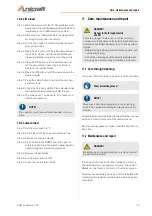
Page 13: ...al is heard throughout the lowering process Step 5 Remove rubber blocks Step 6 Set the main switch to OFF Step 7 Lower the vehicle from the lift 11 Care maintenance and repair 11 1 Care through cleani...

Page 14: ...fety de vices Check the amount of oil remaining in the oil tank The amount of oil is sufficient if the lift can be rai sed to the highest position Otherwise the oil quan tity is insufficient Monthly C...

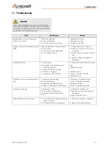
Page 15: ...ighten if necessary Increase too slow 1 Low oil level 2 The pressure relief valve is not correctly adjusted 3 Load to be lifted too heavy 4 Oil filter is clogged 5 Cylinder seal is defective 1 Check o...

Page 16: ...sumption of raw materials For more information about recycling this product contact your local community mu nicipal waste management or the shop where you pur chased the product 14 Spare parts 14 1 O...

Page 17: ...drawings In case of service the following drawing shall help to identify the necessary spare parts If necessary send a copy of the parts drawing with the marked components to your authorised dealer S...

Page 18: ...18 SHB 3 Version 1 02 Electrical circuit diagram Spare parts drawing 2 Fig 19 Spare parts drawing 2 15 Electrical circuit diagram Fig 20 Electrical circuit diagram...

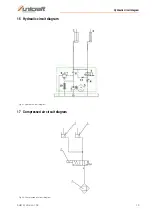
Page 19: ...Hydraulic circuit diagram SHB 3 Version 1 02 19 16 Hydraulic circuit diagram Fig 21 Hydraulic circuit diagram 17 Compressed air circuit diagram Fig 22 Compressed air circuit diagram...

Page 20: ...K Ltd Level 7 Westgate House Westgate Road London W5 1YY UK Kenn Nr 1105 and complies with all relevant provisions of the above mentioned directive and the other directives applied hereafter referred...

Page 21: ...Notes SHB 3 Version 1 02 21 19 Notes...

Page 22: ...www unicraft de...

Reviews: