background image

10

Problem

Suggestion

Unit does not power on.

Check the ignition key position.
Check all connections to the DC power cord as 
well as the fuse inside the holder.  If fuse is out, 
replace with a 4-ampere, 3AG fuse only. 
Check the vehicle electrical system.

No reception.

Make sure the microphone is properly connected.
Set the 

CB/PA

Switch to 

CB.

Adjust the squelch and volume.
Make sure that the antenna and its connections 
are not broken.
Set the 

RF

Gain to the full

clockwise position.

Poor reception.

Adjust the squelch and volume.
Check to see that the antenna SWR is 

2

or below.

Set the 

RF GAIN

to the full 

clockwise position.
Check the Mode Selector setting.  If an SSB signal 
is being received, switch to the proper mode 
setting (

USB

or 

LSB

).

Adjust the Clarifier Control.

No transmission.

Set the 

CB/PA

Switch to 

CB

.

Make sure that the microphone is 
properly connected.
Set the 

MIC GAIN

knob to the full 

clockwise position.

Low transmission.

Check to see that the antenna 

SWR

is 

2

or below.

Set the 

MIC GAIN

knob to the full clockwise 

position.

If you do not get satisfactory results after performing the above checks, call the

Uniden Customer Service Center 

at (800) 297-1023, 8:00 a.m. to 5:00 p.m. CST,

Monday through Friday. 

Do not return this product to the place of purchase.

Our Uniden Representatives will be happy to help you with any question
regarding the operation of this unit, available accessories or any other
related matter.

T

Trro

ou

ub

blleessh

ho

oo

ottiin

ng

g

Grant LT.qxd  3/31/99  10:03 AM  Page 10

Summary of Contents for Grant LT

Page 1: ...COVER ...

Page 2: ...ntive Maintenance 9 Maintenance 9 Troubleshooting 10 Servicing Your Transceiver 11 Radio Code Definitions 12 Specifications 13 Warranty 14 Carefully unpack your Grant LT and check the contents against this list n Grant LT SSB AM Mobile Transceiver n Microphone n Microphone Hanging Kit n Mounting Bracket Kit n DC Power Cord n Reference Guide n Part 95 Subpart D FCC Rules n Product Registration Card...

Page 3: ... Em me er rg ge en nc cy y O Op pe er ra at ti io on n E El li im mi in na at ti io on n o of f L Li ic ce en ns si in ng g The Citizens Band Radio Service is under the jurisdiction of the Federal Communications Commission FCC Any adjustments or alterations which would alter the performance of the transceiver s original FCC type acceptance or which would change the frequency determining method are...

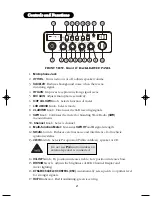
Page 4: ...s 10 Channel Knob Selects channel 11 Multi function Meter Measures SWR RF and S signal strength 12 NB ANL Switch Reduces external noise and interference from vehicle ignition systems 13 CB PA Switch Selects PA optional Public Address speaker or CB 14 HI LOW Switch Hi position increases treble Low position increases bass 15 BRT DIM Switch Adjusts the brightness of LED Channel Display and meter ligh...

Page 5: ...m 4 watt Public Address speaker 21 EXT SP Connects optional 8 ohm 4 watt speaker to remotely monitor receiver 22 POWER Connects DC power to transceiver When the external speaker is plugged in the internal speaker is off To prevent acoustic feedback separate the microphone from the speaker when operating the PA at high output levels ...

Page 6: ...ECTING THE POWER CORDS 1 Check the vehicle battery connections to determine which battery terminal positive or negative is grounded to the engine block or chassis Most of today s vehicles use a negative ground If your vehicle has a negative ground follow steps 2 and 3 2 Connect the RED wire of the DC power cord to the accessory contact in your vehicle s 13 8 VDC fuse box 3 Connect the BLACK wire o...

Page 7: ...onnect an optional external speaker to the External Speaker Jack on the rear of the transceiver For the external speaker use an 8W speaker with at least a 4 watt rating When connected the external speaker automatically disables the internal speaker The external speaker will provide high performance remote receiver monitoring Connecting a Public Address PA Speaker Optional Connect an optional Publi...

Page 8: ...rm the following steps 4a Turn SQUELCH fully clockwise so only strong signals can get through 4b Turn SQUELCH fully counter clockwise until you hear a hiss Everything gets through noise weak signals and strong signals 4c Turn SQUELCH back clockwise until the hiss stops Only clearer signals get through Be sure that the power source antenna and microphone are properly connected before proceeding T T...

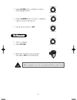
Page 9: ...nob to reduce or eliminate adjacent channel interference 7 Set the meter selector to S RF 1 Select a channel 2 Adjust MIC GAIN 3 When the channel is clear press the microphone PTT switch and speak T To o T Tr ra an ns sm mi it t If the channel is busy do not transmit until it becomes clear ...

Page 10: ... using the SWR CAL Control Adjust the needle to the mark Do not talk into the microphone or set the MIC GAIN Control to the MIN position 5 Move the Meter Selector to the SWR position while holding the PTT Switch A reading below 2 is acceptable Higher readings indicate a problem in the antenna system Problems may be caused by humidity vibration or corrosion Check both ends of the coaxial cable conn...

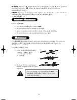
Page 11: ...l cable for wear or breaks in shielding 4 Be sure all screws and mounting hardware are tight The Grant LT is designed to give you years of trouble free service There are no user serviceable parts inside Except for the fuse in the DC power cord no maintenance is required To replace a blown fuse 1 Press ends of the fuse holder together Twist to open Carefully separate the two pieces 2 Remove the fus...

Page 12: ...de Selector setting If an SSB signal is being received switch to the proper mode setting USB or LSB Adjust the Clarifier Control No transmission Set the CB PA Switch to CB Make sure that the microphone is properly connected Set the MIC GAIN knob to the full clockwise position Low transmission Check to see that the antenna SWR is 2 or below Set the MIC GAIN knob to the full clockwise position If yo...

Page 13: ... that this radio is operating at all times in accordance with the FCC Citizens Radio Service regulations We highly recommend that you consult a qualified radio telephone technician for servicing and aligning this CB radio product Please read the Warning information on page 1 of this Guide When ordering parts be sure to specify the correct model number and serial number of the unit ...

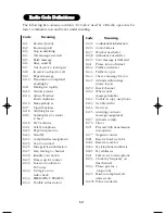
Page 14: ...t 10 30 Does not conform to FCC rules 10 32 I will give you a radio check 10 33 EMERGENCY TRAFFIC 10 34 Trouble at this station Code Meaning 10 35 Confidential information 10 36 Correct time is 10 37 Wrecker needed at 10 38 Ambulance needed at 10 39 Your message is delivered 10 41 Please turn to channel 10 42 Traffic accident at 10 43 Traffic tie up at 10 44 I have a message for you 10 45 All unit...

Page 15: ...B 300 to 3000 Hz Output Impedance 50 ohm unbalanced Output Indicators Meter shows realtive RF output power and SWR Transmit LED glows red when transmitting Receiver Sensitivity SSb 0 25 µV for 10 dB S N N at greater than 1 2 watt of audio output AM 0 5 µV for 10 dB S N N at greater than 1 2 watt of audio output Selectivity AM 6 dB 3 kHz 50 dB 9 kHz SSB 6dB 1 1kHz 60dB 2 3kHz Image Rejection More t...

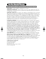
Page 16: ...e unit with a new or refurbished unit THE LIMITED WARRANTY SET FORTH ABOVE IS THE SOLE AND ENTIRE WARRANTY PERTAINING TO THE PRODUCT AND IS IN LIEU OF AND EXCLUDES ALL OTHER WARRANTIES OF ANY NATURE WHATSOEVER WHETHER EXPRESS IMPLIED OR ARISING BY OPERATION OF LAW INCLUDING BUT NOT LIMITED TO ANY IMPLIED WARRANTIES OF MERCHANTABILITY OR FITNESS FOR A PARTICULAR PURPOSE THIS WARRANTY DOES NOT COVER...

Page 17: ...back cover ...
Reviews: