background image

DIN Installation

11

UNIDEN PRO5050

AM-CB Transceiver

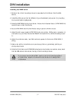
Installing the DIN Bracket


1. Remove the 4 front mounting screws to separate the front frame from the DIN      

    sleeve. 

2. Install the DIN sleeve into the DIN slot of your dashboard and secure it by bending  

    the top and bottom folding tabs. 

3. Slide the PRO5050 into the front frame. Ensure the threaded holes on PRO5050 line  

    up with holes on the front frame. 

4. Secure PRO5050 onto the front frame using 4 pieces of 6mm screws. 

5. Attach the DC power leads to PRO5050 and your vehicle. RED goes to a positive (+)  

    connection on your fuse block while BLACK connects to the vehicle chassis ground    

    (-). 

6. Attach the antenna cable, rear MIC and rear speaker to the back of PRO5050 if  

    using. 

7. Make sure all the connections are routed away from any potentially pinching or  

    slicing sheet metal.  

8. Slide the front frame (with PRO5050 attached and all cable connections done) back  

    into the DIN sleeve and secure it using 4 front mounting screws.

NOTE

If you plan to use the Rear MIC Jack or connect an external speaker

at a later time, expect to remove the unit for ease of making those

connections.

Summary of Contents for PRO5050

Page 1: ...PRO5050 AM CB Transceiver For more exciting new products please visit our website Australia www uniden com au ...

Page 2: ...amming the Instant Priority Channel 16 Recalling the Instant Channel 16 Transmitting 16 Call Tone Function Wake Up Tones 17 DUAL Watch 17 Scanning 18 Open Scan OS Mode 19 Group Scan GS Mode 19 Priority Watch 20 Add Remove Channels from SCAN Memory 20 Selecting the Call Tone 21 Busy Channel Lockout 21 Roger Beep 22 Key Beep On Off 22 Backlight Level 23 Backlight Colour 23 ANL NB Automatic Noise Lim...

Page 3: ...ect to conditions contained in those licenses Features Transmit Receive 40 channels AM CB Transmission Power 5W LCD Display with Backlight LCD Backlight brightness control HI LO OFF Mobile DIN Size Front Speaker Signal Strength and RF Power S RF Meter Automatic Noise Limiter Noise Blanker ANL NB Instant Priority Channel Programming One touch Instant Priority Channel recalling Dual Watch with Insta...

Page 4: ...form poorly follow these procedures If the transceiver is completely inoperative Check the power cord and fuse If there is trouble with receiving Check the VOLUME control setting Be sure the SQUELCH is adjusted properly Possibly the radio is over squelched If there is trouble with transmitting Check that the transmission line coaxial cable is securely connected to the ANTENNA connector Check that ...

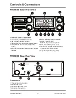
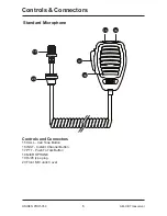
Page 5: ...nd Monitor button 5 ANL NB Automatic Noise Limiter Noise Blanker 11 12 13 14 6 MEM Memory Scan Channels 7 SCAN Scan On Off OS GS Open or Group Scan 8 MIC Front Microphone Jack 9 VOL PWR Rotary Volume Control Power On Off Push control 10 Liquid Crystal Display LCD Controls and Connectors Connectors 11 Power Input Connection 12 Rear MIC Jack 13 External Speaker Jack 14 Antenna Connection PRO5050 Bas...

Page 6: ... CALL Call Tone Button 16 INST Instant Channel Button 17 PTT Push To Talk Button 18 MICROPHONE 19 RJ45 type plug 20 Front MIC Jack Cover Controls and Connectors 6 UNIDEN PRO5050 AM CB Transceiver Controls Connectors 15 16 17 20 19 18 ...

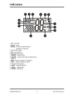
Page 7: ...nel in Memory 4 Channel Number 5 GS Group Scan 6 Signal Power Level 7 ROGER Roger Beep 8 ANL NB Automatic Noise Limiter Noise Blanker 9 S RF Receive Signal or Transmit 10 BCL Busy Channel Lockout 11 Channel Frequency 12 INST Instant Channel 13 DUAL Dual Watch 14 SCAN Scanning 2 3 4 5 6 7 8 1 11 12 14 13 9 10 ...

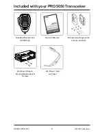
Page 8: ...iver Standard Microphone MK800 s Owner s Manual Microphone Hanger with screws washers DC Power Cord with fuse PRO5050 AM CB Transceiver For more exciting new products please visit our website Australia www uniden com au Din Mount Sleeve Removable Bracket Screws CALL INST ...

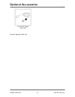
Page 9: ...Optional Accessories 9 UNIDEN PRO5050 AM CB Transceiver External Speaker MS100 Extension Cable EC 770 ...

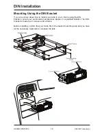
Page 10: ... install your radio in your vehicle using the DIN bracket consult your automobile manufacturer dealer or a qualified installer The DIN bracket is made up of a sleeve and a frame Before installing confirm that your radio fits in the desired mounting area and you have all the necessary materials to complete the task ...

Page 11: ... 6mm screws 5 Attach the DC power leads to PRO5050 and your vehicle RED goes to a positive connection on your fuse block while BLACK connects to the vehicle chassis ground 6 Attach the antenna cable rear MIC and rear speaker to the back of PRO5050 if using 7 Make sure all the connections are routed away from any potentially pinching or slicing sheet metal 8 Slide the front frame with PRO5050 attac...

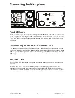
Page 12: ...own along the cord Using the flat blade of a screwdriver or similar object carefully press the lock tab at the bottom of the MIC plug and push it upwards At the same time tug on the MIC cord to draw back the MIC plug Rear MIC Jack Use the Rear MIC Jack if the main base is mounted where a front MIC connection is intrusive Peel the dust cover from the rear MIC jack Push the MIC plug at the end of th...

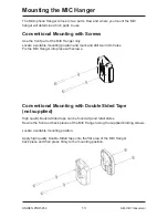
Page 13: ... Locate a suitable mounting position Apply high quality Double Sided tape onto the flat area of the MIC Hanger back piece and then press firmly to the mounting position The Microphone Hanger comes in two parts How and where you mount the MIC hanger will determine which parts to use Conventional Mounting with Screws Use the front part of the MIC Hanger only Locate a suitable mounting position and m...

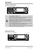
Page 14: ...onds The power source must not exceed 32VDC otherwise permanent damage may occur to your radio which may not be covered by the manufacturer s warranty If the input voltage falls below 10 2VDC LO DC flashes for 5 seconds The power turns off automatically if voltage falls below 9 0VDC Switch your PRO5050 OFF and disconnect it from the power source before locating the cause of the power supply proble...

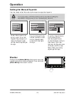
Page 15: ... clockwise it raises the Squelch gate so high that no signals get through If you turn Squelch fully counter clockwise it low ers the Squelch gate so low that noise gets through To set the Squelch Gate to the desired level turn the squelch knob counterclockwise until you hear noise Then care fully turn the Squelch knob clockwise until the noise fades Now only strong signals get through Monitor Pres...

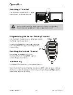
Page 16: ... Channel you prefer Press and hold INST for 2 seconds to store the new setting INST icon appears to designate the Instant channel Recalling the Instant Channel Momentarily press INST to return to the Instant Channel Press INST again to return to the previous channel Transmitting The PRO5050 transmits only on 40 AM CB Channels Select the desired channel Press the microphone s PTT button an speak no...

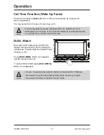
Page 17: ...nd transmission is attempted within one minute then an error tone will sound DUAL Watch Dual watch will continuously monitor the Instant channel and the current channel for activity see Programming the Instant Priority Channel p 16 Press DUAL MON DUAL icon appears and two beeps will sound To cancel DUAL Watch press DUAL MON DUAL icon disappears NOTE Every 1 5 seconds the Instant channel is monitor...

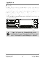
Page 18: ...ou flexibility and allow you to use the radio more effectively Press SCAN OS GS and Scanning starts The SCAN icon appears The scan direction can be changed at any time by rotating the channel selector left or right Operation 18 UNIDEN PRO5050 AM CB Transceiver NOTE By default all channels will be added into scan memory for OS and no channels will be added for GS Please add remove channels accordin...

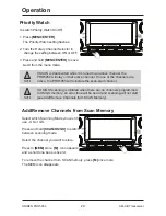
Page 19: ...e the starting channel NOTE OS Mode is indicated by the absence of the GS icon Group Scan GS Mode Includes the accessory feature Priority Watch which allows you to monitor the Instant Priority Channel while scanning see p 16 for setting Instant Priority Channel and p 20 to turn on Priority Watch To use GS Mode Scanning press and hold SCAN OS GS GS icon appears on the display GS Scanning checks the...

Page 20: ...none of the channels are active the PRO5050 will reinstate the scan start channel NOTE If OS GS Scanning is initiated when there are no channels programmed in OS GS memory an error tone will be heard and scanning will not start see Add Remove Channels from SCAN Memory Add Remove Channels from Scan Memory Select which Scanning Mode you wish to use OS or GS Press and hold SCAN OS GS to switch betwee...

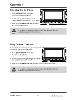
Page 21: ...tton is not pressed within 10 seconds the PRO5050 will automatically exit the Menu Mode Busy Channel Lockout If the channel is already in use you can prevent the AM CB Radio from transmitting 1 Press MENU ENTER three times The BCL setting flashes 2 Turn the Rotary Channel Selector to change the setting between ON or OFF 3 Press and hold MENU ENTER to save exit from the menu mode NOTE If a button i...

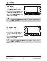
Page 22: ...exit from the menu mode NOTE If a button is not pressed within 10 seconds the Radio will automatically exit the Menu Mode NOTE If a button is not pressed within 10 seconds the Radio will automatically exit the Menu Mode Roger Beep 1 Press MENU ENTER four times The roger beep rb setting flashes 2 Turn the Rotary Channel Selector to change the setting between ON or OFF 3 Press and hold MENU ENTER to...

Page 23: ...nds the Radio will automatically exit the Menu Mode Backlight Brightness 1 Press MENU ENTER six times The Backlight level LIGHT setting flashes 2 Turn the Rotary Channel Selector to change the setting between Off Hi and Lo 3 Press and hold MENU ENTER to save exit from the menu mode NOTE If a button is not pressed within 10 seconds the Radio will automatically exit the Menu Mode ANL NB Automatic No...

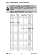
Page 24: ... 235 24 26 600 25 27 245 25 26 610 26 27 265 26 26 630 27 27 275 27 26 640 28 27 285 28 26 650 29 27 295 29 26 660 30 27 305 30 26 670 31 27 315 31 26 680 32 27 325 32 26 690 33 27 335 33 26 700 34 27 345 34 26 710 35 27 355 35 26 720 36 27 365 36 26 730 37 27 375 37 26 740 38 27 385 38 26 750 39 27 395 39 26 760 40 27 405 40 26 770 AM CB Channels Frequencies NOTE The PRO5050 will operate on the f...

Page 25: ...nfigurations not sold by Uniden Aust C Improperly installed contrary to instructions contained in the relevant Owner s Manual D Repaired by someone other than an authorized Uniden Repair Agent in relation to a defect or malfunction covered by this warranty or E Used in conjunction with any equipment parts or a system not manufactured by Uniden Parts Covered This warranty covers the Product and inc...

Page 26: ... case may be none of which can be excluded Procedure for obtaining warranty service Depending on the country in which the Product was first purchased if you believe that your Product does not conform with this warranty you should deliver the Product together with satisfactory evidence of your original purchase such as a legible copy of the sales docket to Uniden Please refer to the Uniden website ...

Page 27: ......

Page 28: ... 2015 Uniden Australia Pty Limited Printed in Vietnam U01UT413ZZZ 0 ...

Reviews: