Assembly/Disassembly
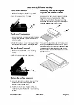
Top Cover Removal
1 .
Remove two top cover retaining screws.
2.
Lift the top cover from the radio.
Top Cover Replacement
1 .
Align the tabs on the top cover with the slots
on the radio and firmly press the top cover
onto the radio.
2.
Ho
l
d the top cover in p
l
ace while you install
and tighten the top cover retaining screws.
Bottom Cover Removal
1 .
Remove the two bottom cover retaining
screws.
2.
Lift the bottom cover from the radio.
Bottom Cover Replacement
1.
Align the tabs on the bottom cover with the
slots on the radio and firmly press the
bottom cover onto the radio.
2.
Hold the bottom cover in place while you
install and tighten the bottom cover retaining
screws.
Removing and Replacing the
Logic Board Ribbon Cables
Use caution when you remove or replace
the ribbon cables that attach to J602,
J605, and J606. Slide the sleeve on the
top
of the connector away from the ribbon
cable to release the r
i
bbon c
a
ble
.
The sleeve should also be in this position
when you replace the ribbon cable. When
the ribbon cable is correctly inserted in the
connector, slide the sleeve on the top of
the connector towards the ribbon cable to
lock it in place.
December 1 992
SMH 4000
Page 23
Summary of Contents for SMH 4000
Page 20: ...Page 20 SMH 4000 December 1 992 ...
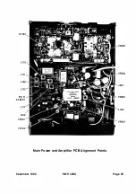
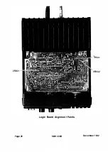
Page 24: ..._TP601 VR602 Logic Board Alignment Points Page 26 SMH 4000 December 1 992 ...
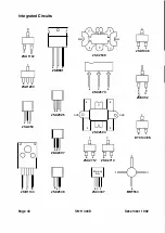
Page 26: ...Page 28 SMH 4000 December 1 992 ...
Page 27: ......
Page 47: ...CC SM 38 Revision 1 SMH 4000 December 1 992 ...
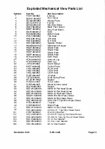
Page 49: ...SMH 4000 Exploded Mechanical View Page 1 8 S M H 4000 I 0 I 0 0 a 3 December 1 992 ...
Page 62: ... I December 1 992 SMH 4000 Earlier Version Logic PCB PD 304AC Component Side SMH 4000 Page 39 ...
Page 72: ......

