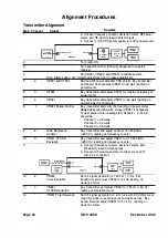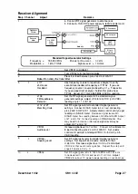
Receiver Alignment
Step Channel
Adjust
Remarks
1
2
3
4
5
1
6
7
8
9
1
1 0
4
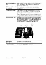
Frequency
Counter
Deviation
Meter
+13.s voe
Power
Supply
a. Connect RF signal generator to antenna jack.
b. Connect
+
1 3.6 VDC power supply to radio's power cord.
Pin 1 1
of
IC1 01
SMU WO
Oscilloscope
DC Voltmeter
AC Voltmeter
SINAD
Meter
RF Sig
n
al
Generator
Standard Signal Generator Settings
Frequency
=
Modulation
=
1 60.050 M
Hz
Modulation Deviation
3.0 kHz
1 kHz TONE
Signal Level
=
1 mVrms
Set VR1 01 to midpoint.
Tum VR1 02 fully counterclockwise.
Place 8
n
load between pins 2 and 3 of WA 1 01 .
Note:
Do not key the transmitter.
L 1 1 7
Use frequency counter or spectrum analyzer to verify
2nd Local
second local oscillator frequency at TP1 02. If you use
Oscillator
frequency counter, couple probe with a 0.1
µ
F capacitor.
L1 09
FM Quadrature
Detector
L1 1 2 , L1 27
Matching Coils
VR 1 01
Audio Level
VR1 02;,
Squelch Level
VR602
If you use spectrum analyzer, hold sniffer probe near
TP1 02. Adjust L 1 1 7 for 44.645 MHz (±50 Hz) reading.
Set the RF signal generator to the standard signal
generator settings. Adjust L 1 09 for 2.6 VDC (±0.5 VDC)
reading at pin 1 1
of
IC1 02.
Set RF signal generator to standard signal generator
settings. Connect
SINAD
meter to
8 n
load
connecting
pins 2 and 3 of WA 1 01 . Adjust volume control until you get
reading on S INAD meter.
Decrease signal level
until
SINAD meter has reading between
1 2
dB and 6
dB.
Adjust
L
1 27 and
L
1 1 2 for best reading on
S INAD meter. You
may need
to increase or decrease
signal level as you
adjust L 1 27 and L1 1 2.
I ncrease signal level to
1 mVrms. Connect AC
voltmeter to
8 load connecting pins 2
and
3
of
WA 1 01 . Set volume
control at maximum a nd adjust VR 1 01
for
5 VAC (±0.5
VAC) reading.
Set
R F
signal generator to standard signal generator
settings. Set squelch and volume controls to their
midpoints.
Decrease signal level to 0.2
µ
V and adjust
VR 1 02 so that audio j ust squelches. Repeat this step until
squelch opens at 0.2 µ V
Set R F signal generator to 1 60 . 050 MHz with 1 67 . 9 Hz
tone deviated to 750 Hz and l evel of 1 mVrms.
Adjust
VR602 for about
1
V peak-to-peak reading on osci lloscope.
December
1 992
SM H 4000
Page 27
Summary of Contents for SMH 4000
Page 20: ...Page 20 SMH 4000 December 1 992 ...
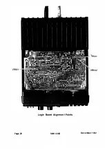
Page 24: ..._TP601 VR602 Logic Board Alignment Points Page 26 SMH 4000 December 1 992 ...
Page 26: ...Page 28 SMH 4000 December 1 992 ...
Page 27: ......
Page 47: ...CC SM 38 Revision 1 SMH 4000 December 1 992 ...
Page 49: ...SMH 4000 Exploded Mechanical View Page 1 8 S M H 4000 I 0 I 0 0 a 3 December 1 992 ...
Page 62: ... I December 1 992 SMH 4000 Earlier Version Logic PCB PD 304AC Component Side SMH 4000 Page 39 ...
Page 72: ......

