Instal lation
Planning the Installation
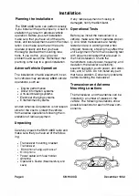
The SMH 4000 radio can perform reliably
If any radio equipment is missing or
damaged, notify the distributor.
if you install all the parts properly. A bad in-
Operational Tests
stallation may result in adverse vehicle
operation. Before you start installation
Before you install the transceiver in a
make sure that you have all of the parts,
vehicle, make sure that it operates proper-
tools, and test equipment used in the instal- ly. All Uniden transceivers are factory
lation. Also make sure that all the parts
tested and are in working order when
operate properly and that you have
shipped; however, shipping may affect the
thoroughly planned the mounting loca-
unit's alignment. Perform an operating test
tions. If you do this, you can avoid
with all parts connected that are used in
problems and save time. Remember that
the final installation. Check the
planning is the key to a good installation.
transmitter's output power, frequency, and
Adverse Vehicle Operation
The installation of radio equipment in cer
tain vehicles may adversely affect vehicle
operations, such as:
•
Engine performance
•
Driver information systems
•
Anti-skid braking systems
•
Electrical charging systems
•
Entertainment systems
Uniden America Corporation is not respon
sible for the cost to protect the vehicle
from adverse operations following the in
stallation of radio equipment.
Unpacking
Carefully unpack the SMH 400D radio and
make sure that you have all of the follow
ing:
•
Transceiver mounting bracket
•
T
r
ansce
i
v
e
r
•
Microphone
hang-up
bracket
•
Microphone
•
Power cable with fuse holder
•
Antenna
•
Operator's Guide
(Read carefully and
save)
deviation; the receiver's sensitivity,
squelch operation, audio power, and distor
tion; and CTCSS. Do not install any part
that has a problem. Correct any problems
before installing the transceiver.
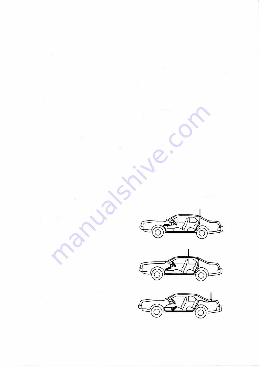
Transceiver and Antenna
Mounting Locations
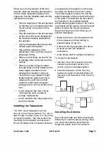
The transceiver, and the antenna can be
installed in a number of places on the
vehicle. The following illustrations show
possible locations for each of these com
ponents.
Page 4
S M H 4000
December
1992
Summary of Contents for SMH 4000
Page 20: ...Page 20 SMH 4000 December 1 992 ...
Page 24: ..._TP601 VR602 Logic Board Alignment Points Page 26 SMH 4000 December 1 992 ...
Page 26: ...Page 28 SMH 4000 December 1 992 ...
Page 27: ......
Page 47: ...CC SM 38 Revision 1 SMH 4000 December 1 992 ...
Page 49: ...SMH 4000 Exploded Mechanical View Page 1 8 S M H 4000 I 0 I 0 0 a 3 December 1 992 ...
Page 62: ... I December 1 992 SMH 4000 Earlier Version Logic PCB PD 304AC Component Side SMH 4000 Page 39 ...
Page 72: ......


