When you plan the location of the com
ponents, keep the following precautions in
mind to make installation easier and to
make sure that the installed parts and the
vehicle work properly:
•
Plan the locations of the components
so that they will not interfere with the
driver's vision or operation of the
vehicle.
•
Plan the locations of the components
so that all controls and displays can
be viewed and easily accessed by
the operator.
•
Avoid unnecessary disturbing of the
vehicle's electrical system.
•
Use existing passages in the
dashboard, trunk, and floor to avoid
excessive drilling.
•
When you drill holes, be careful not
to damage other components of the
vehicle.
•
When you route wiring or cables
through holes or other locations with
sharp edges, be careful not to
damage the insulation. After you
route the wiring or cables through
these locations, seat the wiring or
cables with a grommet or other
means to avoid future insulation
damage due to normal vibration and
use.
•
Avoid locations that may involve
moving parts, such as seat or
window mechanisms.
•
Avoid locations that may expose the
parts to moisture.
Installing the Transceiver
The SMH
4000
transceiver is small
enough to fit almost anywhere. You can in
stall it under the dash, seat, or in any other
convenient location. Plan the location for
mounting the transceiver so that all con
trols and displays can be viewed and easi-
ly accessed by the operator, but the loca
tion does not obstruct the driver's vision.
The antenna cable, power cord, and the
external speaker wiring connect at the rear
of the radio. The radio can be mounted in
any position on any suitable surface
without affecting performance. The mount
ing bracket can be used to mount the radio
above or below the mounting surface.
Keep the following in mind when you in
stall the transceiver:
•
Make sure that air can circulate around
the transceiver and that nothing is
placed directly on top of it.
•
Check all moving seat parts and doors
to avoid contact with cables or
connectors.
•
Allow ample room to access connectors.
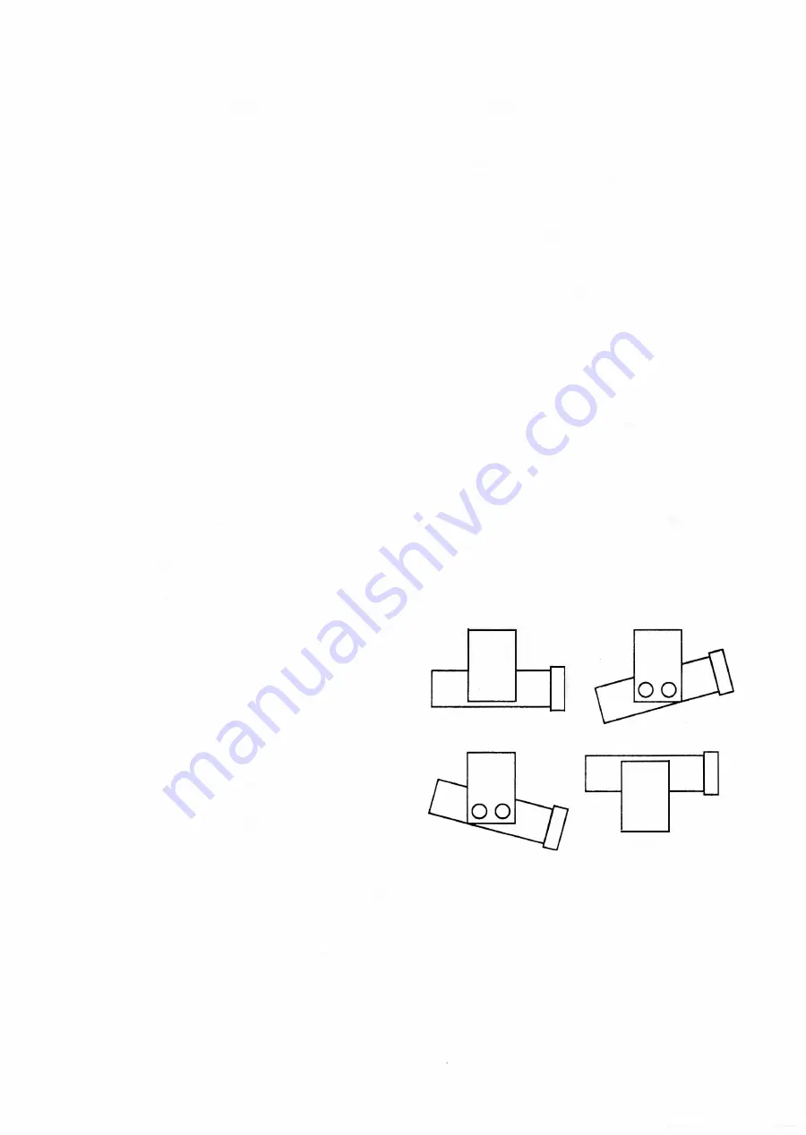
To install the transceiver:
1.
Securely mount the transceiver m ounting
bracket to
a
structural mem ber of the
v
eh
ic
le
,
u
s
i
ng the h
a
rdw
ar
e pr
ovi
ded
.
2. Slide the transceive r i nto the mounting
bracket
a
nd t
i
gh
t
en the
knurled knobs
until
they secure the transceiver to the m ounting
bracket.
00
00
Installing the Antenna
Each vehicle model and body style reacts
differently to radio frequency energy. How
you install the antenna can effect the
range and quality of communications.
December
1 992
SMH 4000
Page 5
Summary of Contents for SMH 4000
Page 20: ...Page 20 SMH 4000 December 1 992 ...
Page 24: ..._TP601 VR602 Logic Board Alignment Points Page 26 SMH 4000 December 1 992 ...
Page 26: ...Page 28 SMH 4000 December 1 992 ...
Page 27: ......
Page 47: ...CC SM 38 Revision 1 SMH 4000 December 1 992 ...
Page 49: ...SMH 4000 Exploded Mechanical View Page 1 8 S M H 4000 I 0 I 0 0 a 3 December 1 992 ...
Page 62: ... I December 1 992 SMH 4000 Earlier Version Logic PCB PD 304AC Component Side SMH 4000 Page 39 ...
Page 72: ......


