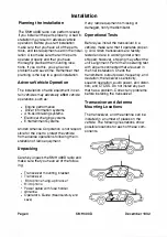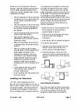
Before you mount an antenna on a
vehicle, use a magnetic mount antenna to
check the proposed antenna location for
any undesired effects on the vehicle. After
you check the proposed antenna location
for problems, mount the antenna used in
the final installation according to the
manufacturer's instructions. The per
manent body mount antenna or the mag
netic mount antenna has the best
performance when mounted in the center
of the roof or rear deck lid. The glass
mount antenna has the best performance
when mounted in the center of the upper
edge of the rear window, side window, or
windshield.
After you mount the antenna, route the an
tenna cable through channels in the
vehicle's body and as far as possible from
the electrical system. This reduces the
amount of RF energy that may leak into
the electrical system. When you route the
antenna coaxial cable through holes or
other locations with sharp edges, be care
ful not to damage the insulation. After you
route the cable through these locations,
seat the cable with a grommet or other
means to avoid future insulation damage
due to normal vibration and use. Make
sure that the coaxial antenna cable is
protected from moisture, moving parts,
and passengers. Connect the antenna
cable to the antenna jack on the
transceiver.
Refer to the antenna manufacturer's in
structions for antenna tuning. This adjust
ment must be done with the antenna and
the radio installed and connected. The an
tenna has the best performance if its volt
age standing
wave
ratio (VSWR)
is kept as
small as possible on all transmit channels.
Do not exceed a
VSWR
of
1.5: 1 .
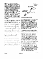
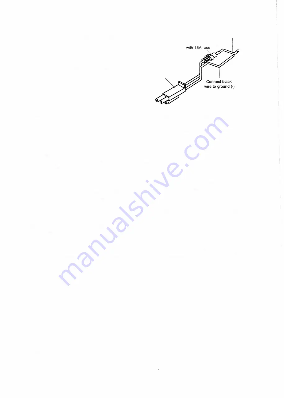
Connect red wire
to positive battery
terminal (+)
Built-in fuse holder
To
SMU 300H/K/M/N
power connector
Connecting the Power
This radio is designed to operate on a 13.6
voe, 10 ampere power source, with a
negative ground. Connect the power
cables directly to the battery terminals. In
stall the inline fuse holder as close as pos
sible to the positive terminal of the battery.
Before you connect the power cable to the
transceiver, make sure
that
all of its
fuses
are properly installed. Connect the wires in
the power cable as follows:
•
Red wire to positive terminal of battery.
•
Black wire to negative terminal of battery.
If the transceiver is not mounted in the
dash area, route the power cable to the
door sills and along the door sills to the
dash area. From the dash area, route the
power cable through the fire wall into the
engine compartment and then to the bat
tery. If the power cables must cross to the
other side of the vehicle, route the cables
to the front
of the engine compartment and
then cross over to the battery. When you
route the power cable through holes or
other locations with sharp edges, be care
ful not to damage the insulation. After you
route the power cable through these loca
tions, seat the power cable with a grommet
o
r other means to avoid future insulation
damage due to normal vibration and use.
Make sure that the power cable is
Page 6
SMH 4000
December 1 992
Summary of Contents for SMH 4000
Page 20: ...Page 20 SMH 4000 December 1 992 ...
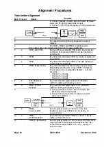
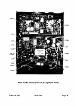
Page 24: ..._TP601 VR602 Logic Board Alignment Points Page 26 SMH 4000 December 1 992 ...
Page 26: ...Page 28 SMH 4000 December 1 992 ...
Page 27: ......
Page 47: ...CC SM 38 Revision 1 SMH 4000 December 1 992 ...
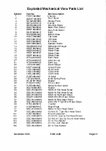
Page 49: ...SMH 4000 Exploded Mechanical View Page 1 8 S M H 4000 I 0 I 0 0 a 3 December 1 992 ...
Page 62: ... I December 1 992 SMH 4000 Earlier Version Logic PCB PD 304AC Component Side SMH 4000 Page 39 ...
Page 72: ......


