49
Motorola Reception
Motorola Tracking
There are really two types of Motorola trunking systems. These are usually referred to as
Type I and Type II systems. Type I only occurs on some 800 MHz systems. All VHF, UHF
and 900 MHz trunking systems use Type II.
One important distinction between these two systems is the amount of data transmitted by
each radio when its push-to-talk button (PTT) is pressed. Every radio in a trunked system is
assigned a unique ID so the central site computer can identify it when it’s used. Both Type I
and Type II systems place radios (or radio users) into groups, called talkgroups, and these
talkgroups are also assigned unique IDs. Some radios have access to only one talkgroup,
while others have access to many talkgroups. The talkgroup(s) each radio can access is
called the radio’s affiliation(s).
In a Type II system, when someone uses their radio, only the radio ID is transmitted when
PTT is pressed, whereas in a Type I system the radio ID and its current affiliation are both
transmitted when PTT is pressed.
Why the difference? Type II systems are slightly more advanced because the central
computer maintains a database which is used to determine each radio’s affiliation (s).
Changes to a Type II system are easier than Type I because the system manager only
needs to update the database instead of reprogramming individual radios.
Another difference between the systems is that Type I systems are arranged in a Fleet-
Subfleet hierarchy. For example, its possible for a city using a Type I system to designate 4
Fleets, each with 8 Subfleets. Their fleets might be the Police Department, the Fire
Department, Utilities, and Administration. The Police may decide to further divide their fleet
into subfleets such as Dispatch, Tactical Operations, Detectives, North, South, East and
West Side Patrols, and Supervisors. All the available police radios would then be assigned
to one of the police subfleets. Determining the exact Fleet-Subfleet hierarchy for a particular
area is referred to as Fleet Map Programming, which is discussed further in this manual.
The disadvantage of a Type I system is that when PTT is pressed, the brief burst of data
must contain the radio’s ID and its Fleet and Subfleet. This is three times the amount of data
a Type II system radio sends, and as a result Type I systems usually accommodate fewer
users than Type II systems.
Even though there are many Type II systems, Type I systems are still in use. There are also
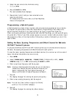
Hybrid systems which are a combination of both Type I and Type II. Your scanner defaults to
monitor Type II systems, but its possible to select a Preprogrammed Fleet Map or create a
Custom Fleet Map for your area.
For VHF and UHF Type II trunking systems, you will need to know the base, spacing
frequencies and offset channels. See page 51 for details.
Summary of Contents for UBC780XLT
Page 1: ...500 Channel Trunk Tracking Scanner UBC780XLT TRUNKTRACKER III...
Page 5: ...NOTE SMART SCAN NOT APPLICABLE IN AUSTRALIA UBC780XLT Flow Charts...
Page 6: ...UBC780XLT Flow Charts continued...
Page 7: ...UBC780XLT Flow Charts continued...
Page 8: ...UBC780XLT Flow Charts continued...
Page 81: ...71 CTCSS Frequency List Hz DCS Tone Code...
Page 82: ...72 Memo...
Page 83: ...73 Memo...
Page 84: ...74 Memo...
Page 86: ...NOTE SMART SCAN NOT APPLICABLE IN AUSTRALIA UBC780XLT Flow Charts...
Page 87: ......
Page 88: ...UBC780XLT Flow Charts continued...
Page 89: ......

