background image


UIP200 User's Manual 


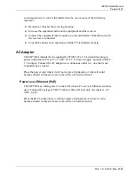
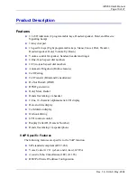
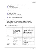
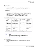
Page 16 of 27 


Rev. 1.0, © UAC, May, 2004 

Basic Telephone Operations 

Standby 

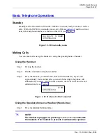
Standby mode is the state in which the UIP200 is on-hook, ready to make or receive 
calls. While the UIP200 is in standby mode, all LEDs are turned off and the current 
date, time and phone number are shown on the LCD (see Figure 3).  


Figure 3  LCD in standby mode 

Making Calls 

You can make calls using the handset or using the speakerphone or headset. 

Using the Handset 

Step 1:  Pick up the handset. 

Step 2:  Dial the destination telephone number. 

Step 3:  Press the 

DIAL


key to initiate the connection immediately. If you wait 

approximately four seconds after you enter the last digit, the phone will 
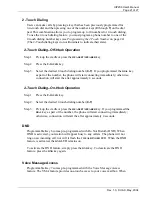
automatically connect. After the call connects, the LCD will show the call 
duration timer (see Figure 4). 


Figure 4  LCD when a Call is Connected 

Using the Speakerphone or a Headset (Hands-free) 

Step 1:  Press the

 HEADSET

/

SPEAKER

 key.  

NOTE: 
If a headset is plugged in, pressing 

HEADSET

/

SPEAKER

 activates 

the headset. If no headset is present, it activates the speaker. 

            0:04

5555553154 

01/01/70  9:00AM

5555551234 

Summary of Contents for UIP200 - VoIP Phone

Page 1: ...your UIP200 SIP IP phone It provides a description of the telephone s hardware features LCD displays and explains setup configuration and basic operation If you have any questions about the informatio...

Page 2: ...ew 6 Important Safety Considerations 7 Important Electrical Considerations 8 The FCC Wants You to Know 8 AC Adapter 9 Power over Ethernet PoE 9 Product Description 10 Features 10 VoIP Specific Feature...

Page 3: ...Operation 19 Hold 19 Feature Operations 20 Programmable and Fixed Function Keys 20 1 Touch Dialing 20 2 Touch Dialing 21 DND 21 Voice Message Access 21 Mute 22 Dial fixed key 22 Emergency Proxy 22 Con...

Page 4: ...te 14 Figure 3 LCD in standby mode 16 Figure 4 LCD when a Call is Connected 16 Figure 5 LCD display when Receiving a Call 17 Tables in This Document Table 1 Revision History 6 Table 2 Control Keys and...

Page 5: ...by government regulation or company policy CAUTION Cautions appear with the slow sign They indicate there is a danger of damaging the equipment or causing a mission critical problem if the instructio...

Page 6: ...appropriate electric inspection authority or electrician as appropriate Hearing Aid Compatibility The equipment is hearing aid compatible Recording Conversations The act of monitoring or recording te...

Page 7: ...e marking label If you are not sure of the type of power supply to your home consult your dealer or local power company Do not allow anything to rest on the power cord Do not locate this product where...

Page 8: ...ted to it This product is no exception WARNING Do not attempt to unplug any appliance if lightning is already present The FCC Wants You to Know Changes or modifications to this product not expressly a...

Page 9: ...32 a UL Listed direct plug in power unit marked Class 2 or LPS or I T E Power Supply and rated 5VDC 1 7A output Connect the AC adaptor to a continuous outlet i e one that is not controlled by a switch...

Page 10: ...l numbers Automatic Ringdown Hotline feature Call Waiting Call Transfer Blind and Consultation Do Not Disturb DND DTMF generation Hold Mute Redial Hands free talking via headset 2 line 16 character al...

Page 11: ...ntrol Keys and Their Functions Key Situation Operation HEADSET SPEAKER On a call Turns speakerphone headset on and off HOLD On a call Places the remote party on Hold One caller is on the line Transfer...

Page 12: ...programmable function keys these keys illuminate when they are used Table 3 LEDs and Their Meanings LED LED On LED Blinking LED Off All LEDs The phone has powered up and is initializing N A The phone...

Page 13: ...ase T RJ 45 LAN connection 10 100 Base T RJ 45 Handset connection RJ 22 x 1 Headset Phone Jack 2 5mm X 1 DC Jack EIAJ Class2 Center X 1 Power Supply Input to the phone from the power supply 5 Vdc 1 7...

Page 14: ...tached one way Once the bracket is attached the phone may be mounted over an existing wall plate Figure 1 Attaching the Wall Mount Bracket Attach the wall mount bracket to the rear of the phone Be sur...

Page 15: ...C power supply Step 1 Connect the handset to the handset port RJ 22 located on the left side of the phone as viewed from the front of the phone Step 2 Connect the Ethernet cable from the network to th...

Page 16: ...sing the Handset Step 1 Pick up the handset Step 2 Dial the destination telephone number Step 3 Press the DIAL key to initiate the connection immediately If you wait approximately four seconds after y...

Page 17: ...y to initiate the connection if you wait approximately four seconds after you enter the last digit enter the phone will automatically connect Receiving Calls When there is an incoming call the VISUAL...

Page 18: ...is saved Changing the Speakerphone Volume Step 1 If a headset is plugged into the phone unplug the headset Step 2 Press the HEADSET SPEAKER key Step 3 Press UP or DOWN to adjust the volume Step 4 When...

Page 19: ...one and transferring the call Call Waiting Operation Step 1 If the call waiting feature is enabled you will hear a call waiting tone when another call comes in while you are on the line Step 2 Press t...

Page 20: ...1 Touch Dialing Programmable Keys 1 through 4 come pre programmed with 1 Touch dialing feature To use the 1 Touch dialing feature you must program a phone number to one of the 1 touch programmable ke...

Page 21: ...rt connecting immediately otherwise connection will start the after approximately 4 seconds 2 Touch Dialing On Hook Operation Step 1 Press the 2 TOUCH key Step 2 Select the desired 2 touch dialing num...

Page 22: ...ey 8 is pre programmed as the MUTE key During a call you can press MUTE to disable the microphone on the handset speakerphone or headset While the Mute feature is activated the MUTE LED remains on To...

Page 23: ...gating the Menus The following information will help you understand the interface for the configuration menus Press the MENU key to access the Setup menu Use the and keys to scroll through the menu ch...

Page 24: ...or edit Step 3 If you want to edit the phone number change the number and press the MENU key If you want to clear the phone number simply press the MENU key without editing the phone number Step 4 Yo...

Page 25: ...You can only access the LCD Contrast Adjust Time and Language sub menus The Preferred Codec Factory Reset and Auto Config sub menus are available to administrators only Changing the LCD Contrast The L...

Page 26: ...e will prompt you to edit the day Step 6 If necessary use the number keys to change the day and press MENU The phone will prompt you to edit the hour Step 7 If necessary use the number keys to change...

Page 27: ...ask and Default Gateway All sub menus under Network Setting are password protected and can be altered only by an administrator Users may view the information but not change it View Info The View Info...

Reviews: