background image


16


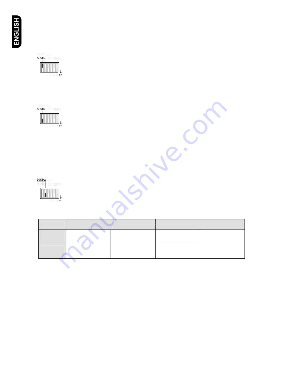
3. Selecting Operation Mode 


Mode 1 

(Mode Dip switch in upward position) 


In operation mode 1 the internal power amp of UCA 8240 is used for background music (BGM) 
and paging signal at the same time.  
 
Both, BGM and paging signals are available at the XLR output named EXT. AMPLIFIER (50)  
If you activate a paging signal via an input that has higher priority than BGM the BGM signal 
will be reduced to the level that has been preset with the VOX Level control (54)  at the rear 
panel. 

 
Mode 2 

(Mode Dip switch in downward position)


In operation mode 2 the internal power amp of UCA 8240 is used for BGM purposes exclusively 
 
The output named EXT. AMPLIFIER (50) has to be connected to the input of an external power 
amp and the 100V input named EXT. AMP IN (56) has to be connected with the output of the 
external power amp.  
 
If you activate a paging signal with a higher priority as the BGM signal, the paging signal will be 
routed via the EXT. AMPLIFIER (50) to the external power amp  
 
The 100V output signal of the external power amp is fed back to the EXT. AMP IN (56) input of 
the UCA 8240. Zones not selected for the paging signal will continue reproducing the BGM 
signal via the internal power amp of the UCA 8240 


Selecting the 20kHz Pilot Tone 


If the dip switch (24) is in it’s downward position the surveillance function of the power amp is 
activated  
 
If a malfunction of the power amp  for the paging signal is detected the UCA 8240 will 
automatically switch to the power amp that was previously used for BGM. Furthermore the red 
Fault LED (10) on the front panel of UCA 8240 will light up. 


Operation Mode 1 

Operation Mode 2 


Normal 

In Case of Fault 

Normal 

In case of Fault 

Internal 

Power Amp 

BGM & Paging 

BGM 

External 

Power Amp 

Spare power amp 

Paging Signal is routed via 

the external power amp. 

Paging 

Paging Signal is routed via 

the internal  power amp.. 


As you can see from the above table the paging function is  assured even if the power amp used for paging 
fails. 
 
If the power amp used for BGM fails the Fault LED will also light up but there will not be a switch over to the 
spare amp.  
 

Summary of Contents for UCA 8240

Page 1: ...6 Zonen Kompaktverst rker 6 Zone Compact PA System UCA 8240 Bedienungsanleitung User Manual...

Page 2: ...ikrofoneingang verf gt ber eine eigene Klangeinstellung f r H hen und Tiefen Die Eing nge MIC 5 LINE 1 und MIC 6 LINE 1 k nnen f r Eingangssignale mit unterschiedlichen Pegeln verwendet werden Die 6 M...

Page 3: ...8 8 Eingang f r externe Hintergrundmusik 9 9 Nutzung des Priorit tseingangs 9 10 Nutzung des MOH Ausgangs 10 11 Verwendung des Wandbedienpanel UWC 8006 10 12 Ausgang f r eine externe Endstufe 11 13 A...

Page 4: ...en und Tiefen 7 AUX 1 bis 3 und Internal Source Wahlschalter Anzeigen Durch mehrfaches Bet tigen dieser Taste schalten Sie zwischen AUX 1 bis 3 und SOURCE Eing ngen um 8 MASTER Pegeleinsteller Zur Peg...

Page 5: ...r MIC 5 Line 1 33 Audioeingang MIC 5 Line 1 34 Mikrofoneingang MIC 4 35 Dipschalter zum Aktivieren der Phantomspeisung f r MIC 4 und MIC 3 36 Mikrofoneingang MIC 3 37 Mikrofoneingang MIC 2 38 Dipscha...

Page 6: ...en Eingang EXT AMP IN 56 zur ckgef hrt Die nicht ausgew hlten Zonen werden w hrend der Sprachdurchsage weiterhin von der internen Endstufe des UCA 8240 mit dem 100V Audiosignal der Hintergrundmusik ve...

Page 7: ...r Amplifier Max output power 360W Rated output power 240W 115 230V 50 60Hz RoHs Um den RJ45 Sprechstellenanschluss mit einer UPM 8001 Sprechstelle zu benutzen m ssen die Dipschalter 38 PTT und Phantom...

Page 8: ...schbetrieb Alle Mikrofone k nnen parallel betrieben werden Hinweis Wird eine UPM 8001 Sprechstelle verwendet so ist der MIC 1 Eingang vom gestellten Priorit tsmodus nicht betroffen Konfiguration der M...

Page 9: ...teuerter Eingang mit der h chsten Priorit t Low Pegel Eingang 46 An den Klemmen GND k nnen sie ein symmetrisches Low Pegel Signal einspeisen Die Eingangsempfindlichkeit betr gt 100mV bei 600 Ohm der A...

Page 10: ...g des Wandbedienpanels UWC 8006 Remote Master On Off UWC8006 1 2 3 Sour ce Aux Select MIX Level Line In MI C To UCX 8012 Das UWC 8006 Wandpanel wird ber ein RJ45 Kabel mit dem Wall Control Panel Ansch...

Page 11: ...entnehmen Sie bitte der UCX 8012 Bedienungsanleitung Mit den Tasten die sich unter den Pegelstellern 14 f r die Zonen 1 bis 6 befinden k nnen Sie die entsprechende Zone ein und ausschalten Bei einges...

Page 12: ...s it s own separate tone controls for treble bass The inputs MIC 5 LINE 1 and MIC 6 LINE 1 can be used for input signals with different levels mic or line The 6 mic inputs can be operated with 4 diffe...

Page 13: ...7 7 Microphone inputs 18 8 Input for external BGM 19 9 Operation of mic priorities 19 10 Operation of the MOH outputs 20 11 Operation with the wall panel UWC 8006 20 12 Output for external power amp 2...

Page 14: ...e adjustment of treble and bass for AUX 1 3 7 Selector Switch for AUX 1 3 and internal music source Consecutive pressing this ky allos the seection of the desired inputs AUX 1 3 and Source 8 MASTER le...

Page 15: ...power for MIC 5 Line 1 33 Audio input MIC 5 Line 1 34 MIC 4 input 35 Dip switch to activate phantom power for MIC 4 and MIC 3 36 MIC 3 input 37 MIC 2 input 38 Dip switch to activate phantom power for...

Page 16: ...R 50 to the external power amp The 100V output signal of the external power amp is fed back to the EXT AMP IN 56 input of the UCA 8240 Zones not selected for the paging signal will continue reproducin...

Page 17: ...put power 360W Rated output power 240W 115 230V 50 60Hz RoHs In order to use the RJ 45 connector with the desktop mic UPM 8001 the dip switch 38 PTT and Phantom for Mic 1 must be in the on position do...

Page 18: ...ic is possible Mixing Mode All mics can be operated in parallel Attention A UPM 8001 connected to the Mic1 input is not affected by the selected priority mode selected for the mics 2 6 Configuration o...

Page 19: ...x controlled and has the highest priority Low level input 46 At the terminals GND a balanced low level signal can be fed in The input sensitivity is 100mV at 600 Ohms the muting theshold of the VOX ci...

Page 20: ...Off UWC8006 1 2 3 Sour ce Aux Select MIX Level Line In MI C To UCX 8012 The wall panel UWC 8006 is connected via a RJ45 cable with the WALL Panel connector 49 at the rear of the UCA 8240 The followin...

Page 21: ...ser manual You can select unselect the desired Zone 1 6 with the keys located underneath the volume controls 14 A selected zone is indicated by the lighted green LED above the respective zone key Atte...

Page 22: ...k Ta l k TALK BUSY Lo c k T a lk TA LK Music Source e g UD 1001 Music Source e g UD 1001 UCX 8012 UCX 8012 100V Power Amplifier 100V Power Amplifier 100V Power Amplifier 100V Power Amplifier UCA 8240...

Page 23: ...lanced Eing nge Inputs Wall panel 1V RJ45 connector TEL EMER 100V balanced 100V Eing nge 100V Input Ext Amp In 100V input REC Out 1V unbalanced RCA PRE Out 1V unbalanced RCA Ext Amplifier XLR out 1V b...

Page 24: ...24 UNIelectronic Vertriebs GmbH Steinbrinksweg 25 D 31840 Hessisch Oldendorf Fon 49 5152 52522 0 www unielectronic com...

Reviews: