background image


Close Control Regulation Program 


72 06MC0071@00B0110 

01/10/2012 


DOWNLOAD FROM SMART KEY 

 
Downloading of the LOGS files can also be carried out by a Smart Key. The Smart Key must, however, first of all 
be configured for reading by carrying out the following steps. Connect the Smart Key to the specific converter and 
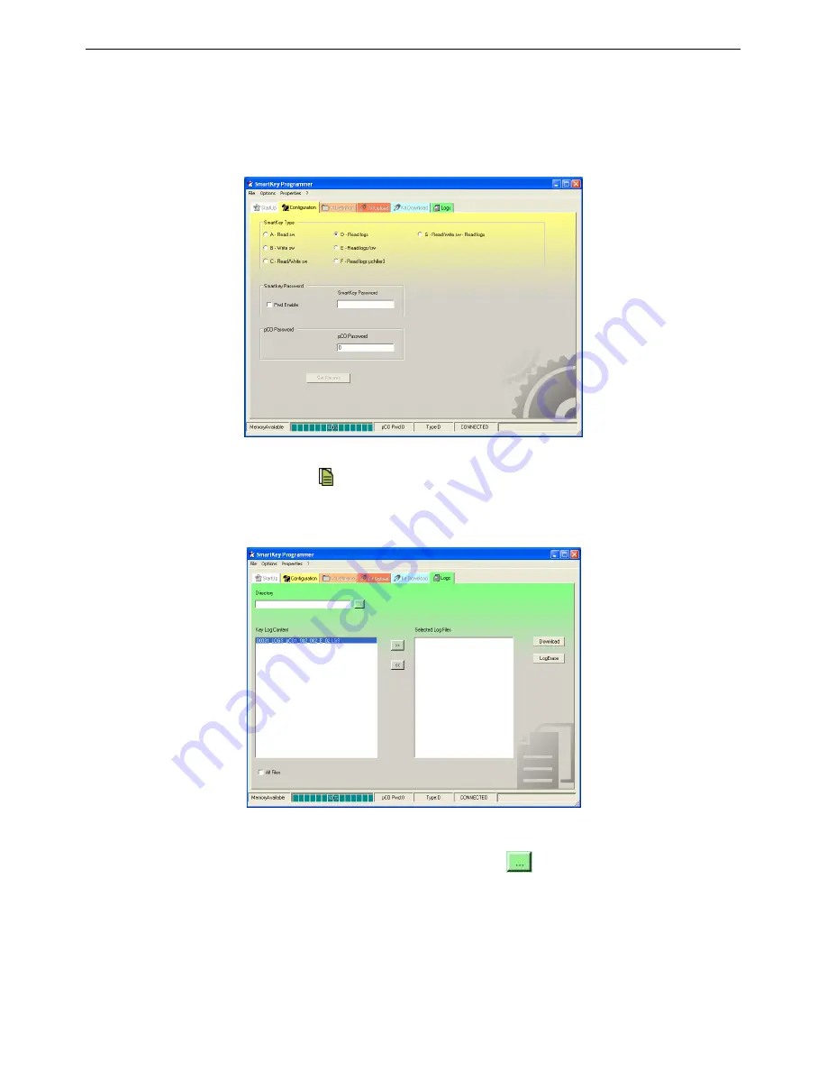
start up the SMART KEY program, access the CONFIGURATION screen and select option “D : Read Logs ”
Once configured, the Smart Key will shut down the program and disconnect the key from the converter. 


To read the LOGS of the UpCO board, switch off the unit, insert the key into the telephonic converter of the board 

and switch it on, wait for the history icon 

to light up on the key and then press the START button and then wait 

until a beep is heard. 
Remove the key from the UpCO board and connect it to the specific converter. Start up the SMART KEY program 
and select the LOGS panel. 


By using the "Directory" field it is possible to type in the name of the directory in which the LOGS downloaded from 

the key are to saved, it is also possible to select the directory by using the 

 button which opens the following 

window. 
 

Summary of Contents for UTS01

Page 1: ...UNIFLAIR Instruction manual UTS01 TOUCH SCREEN TERMINAL FOR CLOSE CONTROL UNITS EN...

Page 2: ...tems defined by local legislation must be used In addition the equipment can be returned to the distributor at the end of its working life when buying new equipment The equipment may contain hazardous...

Page 3: ...STICS 12 DISPOSAL OF THE PRODUCT 12 PLAN NETWORK CONNECTION 13 UNIT START UP CONDITIONS 19 SWITCHING UNIT ON AND OFF 19 PASSWORD 20 VARIATION OF PARAMETERS 21 INFORMATION ON DISPLAY 21 ICONS WHEN THE...

Page 4: ...OPTIONAL SENSOR OR DIGITAL INPUT ALARMS 53 UNIT FUNCTION ALARMS 54 AFPS SENSOR ALARMS 56 ELECTRONIC EXPANSION VALVE ALARMS DX TC ES UNITS ONLY 56 HUMIDIFIER ALARMS 58 SENSOR ALARMS 59 SERVICE NOTE 60...

Page 5: ...e g sulphur or ammonia fumes saline mist smoke so as to avoid corrosion and oxidisation strong magnetic and or radio interference therefore avoid installing the unit near transmitting antennae exposu...

Page 6: ...en together with the up and Prg buttons for at least one second Alternatively press the up down enter buttons together for at least one second The following operations exit the menu 1 pressing the Esc...

Page 7: ...gs SCREEN SETTINGS MENU Fig 6 The following options are available Contrast Used to set the contrast of the display from 0 to 100 default 50 Normal Brightness After Used to set the time after the touch...

Page 8: ...network are configured for this speed Note that not all the pLAN devices support the 115200 setting Network Monitor This is used to display the status of the network see next paragraph Setup I O Boar...

Page 9: ...selected 4 to exit the configuration procedure and save the data select the OK field set Yes and confirm by pressing enter Alternatively if the terminal remains inactive no button is pressed for more...

Page 10: ...ions menu The updates must have previously been loaded onto a UpCO connected in the pLAN network following the instructions provided with the documents on the UpCO application development tools To upd...

Page 11: ...terminal has just been switched on and or is waiting to establish communication Please wait when exiting the procedure for assigning the private or shared terminals for a UpCO No network link terminal...

Page 12: ...tween the wires must not exceed 90 pF m See paragraph CABLE FOR LAN AND SUPERVISION CONNECTION Note to reach the maximum length use a bus layout with branches that do not exceed 5 m FUNCTIONAL CHARACT...

Page 13: ...a pLan connection is shown between units with their own private UTS01 local user terminal and a shared UTS01 remote user terminal Connection to the private UTS01 terminal is made through a J11 termin...

Page 14: ...ngth of the screen should be as short as possible Case C In this diagram a pLan connection is shown between units with their own private UG40 local user terminal a private UTS01 remote user terminal a...

Page 15: ...tion from UTS01 to UG40 In order to activate functioning communication must be switched from UST01 private terminal by following these simple steps 1 Access the Service Menu after having entered the P...

Page 16: ...inal 2 Pressing UP ENTER DOWN set up the private address from the on board UG40 terminal and confirm with ENTER 3 Press again UP ENTER DOWN and then set up the private and shared addresses in the dedi...

Page 17: ...s screen is displayed 3 Modify the address TERMINAL ADDRESS according to which unit must be monitored Example unit 1 address 21 4 Reconnect the terminal of the pLan network pLAN addresses table UG40 P...

Page 18: ...ble conductors made from tin plated copper AWG 22 7 insulated with polypropylene singularly coupled screened with aluminium polyester tape continuity wire in tin plated copper AWG 24 7 connected on a...

Page 19: ...ing hourglass will appear and then a moving fan icon The unit can be switched off from the first screen by keeping the on off button pressed until is shown 2 Automatic mode the unit can be switched on...

Page 20: ...arious menus which can be chosen When the SETTINGS MENU or SERVICE MENU buttons are pressed a screen appears where the password can be entered Type in the correct password and press OK to confirm if a...

Page 21: ...revious screen press the button To modify parameters in other screens press the button until the cursor is at the start of the first line press the or button to move to the desired screen INFORMATION...

Page 22: ...he unit is switched off by the fire smoke alarm 9 the unit is switched off by the flooding alarm 10 the unit is switched off by the air flow alarm 11 the unit is switched off by the elevated air flow...

Page 23: ...percentage It is the same for the second valve 5 Hot gas operation activated The field below the icon indicates the operating status DESCRIPTION OF KEYS INTEGRATED KEYBOARD The UTS01 terminal feature...

Page 24: ...s button a brief description of the different buttons which can be touched appears see the diagram below for an example The HELP function can also be activated in the settings and service menus 2 ON O...

Page 25: ...e values cannot be changed To set the values access the parameters in programming mode and enter the SETTINGS password All variables are pre set in the factory so that the control functions correctly...

Page 26: ...larm event TEMPERATURE HUMIDITY GRAPH This screen can only be seen if there is a flash memory expansion in the UpCO1 board for history and LOG memory see paragraph ESPANSION FLASH MEMORY The graph all...

Page 27: ...focuses on the point indicated on the touch screen by the user on the Trend curve Resets the X and Y coordinates to the default Resets the Y coordinate to the default INPUT OUTPUT On this screen and...

Page 28: ...e humidifier board LAN NETWORK CONNECTION STATUS This screen allows the information from the LAN Network to be displayed From here it is possible to select the required unit by simply touching the ima...

Page 29: ...kload to be shared between the units at programmable time intervals By setting cycle time h 000 the controller runs a test rotating the units at two minute intervals the possibility of having 1 or 2 u...

Page 30: ...on CW mode only SETPOINT FOR A F MASTER This screen is displayed if the unit is connected to a system called MASTER CONTROL which allows the cooling system to be managed thus optimizing operation of t...

Page 31: ...ity sensor Intervention of the set back function must control the room conditions although with larger tolerances even if the whole system is in stand by it s intervention therefore is independent and...

Page 32: ...al output that signals the alarm The configuration of an alarm does not affect the action performed by the controller signal only on the display or shutdown of the device affected by the alarm STAND B...

Page 33: ...T On Off Cycle on the previous screen On the main screen the icon is shown to indicate that the unit is switched off due to a time band HOURMETER SETTINGS This part of the program enables the setting...

Page 34: ...ll of the maintenance operations on the cylinder press Enter to return to normal operating conditions of the humidifier after 2 minutes SERIAL COMUNICATION SUPERVISION SYSTEM a supervision system exch...

Page 35: ...of emergency the individual components can be activated manually and independently of the control process Unit fan Unit start Up Compressor 1 2 3 4 Compressor 1 2 3 4 on CW units analogue output 0 1...

Page 36: ...INGS This screen is used to set Valve Type model of electronic valve used Refrigerant type of refrigerant gas used Low SH Protection activates the LowSH protection which acts rapidly closing the valve...

Page 37: ...ding of the temperature evaporating sensor to be corrected if a difference between the measured value of the sensor and the effective value is detected when measured with a precision instrument The ma...

Page 38: ...ivat Time derivative time Max Suction temp maximum suction temperature Circ EEV Ratio This ratio is expressed as a percentage between the maximum cooling capacity of the circuit regulated by the EVDri...

Page 39: ...it is necessary to re configure the control and to proceed to the setting of the set point when different from those of the default IMPORTANT when a modification is made also when concerning a parame...

Page 40: ...t is the quantity that needs to be added or subtracted to obtain the correct value when measured with a precision instrument SOFTWARE SETTINGS This screen is used to set Integral Time integral time An...

Page 41: ...manage the radiator speed This screen is only available in the Twin cool version and is used to manage the settings for activating the changeover from mechanical cooling operation to operation with ch...

Page 42: ...l control function is activated which acts as follows the controller sends the water chiller a request for water at a lower temperature to allow dehumidification this is done by instantly activating d...

Page 43: ...for switching between these two heating systems Allows you to set the set point that triggers the switching between the two heating systems This screen concerns the behaviour during the initial trans...

Page 44: ...NGS password for the configuration CONFIGURATIONS password or SERVICE password Since access to the HARDWARE menu is denied unless the corresponding password is known the new password should be written...

Page 45: ...4 Refrigerant Circuits identifies the number of refrigerant circuits max 2 Compressor Type identifies the type of compressor installed Amico versions only Heaters identifies the number of operating st...

Page 46: ...ide temperature and humidity sensors that must be connected to a specific input First check that the input is not already occupied given that these are multifunction inputs The table below shows a det...

Page 47: ...ification Fan Speed rated speed in the dehumidification phase for Amico units with mechanical thermostatic valve only Modulation with Air Pressure Enabled enables fan speed modulation with the AFPS sy...

Page 48: ...peed control associated with the opening of the water valve CW version only Minimum Speed minimum fan control speed Maximum Speed maximum fan control speed This screen is used to establish which resou...

Page 49: ...r Timed drains enable enables the procedure for draining the cylinder to avoid the formation of scale inside This screen displayed only if the cylinder cleaning procedure is enabled is used to set Tim...

Page 50: ...s with the timeout for entering the password Buzzer Type enables operation of the buzzer Time ON time the buzzer remains on This screen is used to set the mains frequency automatically or manually COM...

Page 51: ...ed are not memorized and therefore are not able to be read DESCRIPTION OF ALARM EVENTS All of the possible alarm messages which can be displayed on the user terminal are shown below For active alarms...

Page 52: ...is can be delayed during the unit start up phase the default delay is 15 minutes Signal only This can be delayed during the unit start up phase the default delay is 15 minutes Signal only This can be...

Page 53: ...W units Activated by the Smoke Fire sensors and always causes the unit to switch off Activated by the flooding control module or from the condensing discharge pump alarm contact only causes the unit t...

Page 54: ...ch PFS only causes an alarm signal without unit operation being affected Indicates that the air filter needs to be cleaned or replaced Alarm signal activated by from the safety thermostat TSR causes t...

Page 55: ...temperature sensor when the high temperature limit is exceeded TC units only causes the changeover from chilled water operation CW to direct expansion DX It is also displayed when the ambient tempera...

Page 56: ...X TC ES units only These are alarms which are connected to the driver of the EVD400 electronic expansion valve causing the compressor s to switch off Activated when there is low evaporation pressure o...

Page 57: ...d which is longer than the Alarms Delay Low SH Also specifies the number of the circuit Activated following an error in the tLAN connection between the EVD400 driver and the UpCO1 control board Also s...

Page 58: ...he high level electrodes in one of the following cases 1 the unit is disabled or shutdown remote control switch fill and drain OFF 2 before the start of the first pre wash cycle consisting of 10 minut...

Page 59: ...um fill time Warning only SENSOR ALARMS These are activated when there is a malfunction of the sensors or they have been incorrectly connected to the main board If one of these alarms is activated che...

Page 60: ...operating hours of the component are exceeded This type of alarm which continues until the counter is reset is not however memorized in the historical alarm sequence Signal only This may concern the a...

Page 61: ...nfiguration screens by entering the password incorrectly 3 consecutive times NOTE To reset the alarm carry out the following procedure 1 press the Prg key and select the Service Menu 2 enter the corre...

Page 62: ...rial No P1 Delivery SetP C 17 0 14 0 35 0 Motorized damper No P1 Room Temp C 22 0 17 0 35 0 Buzzer enabled Si P2 Delivery SetP C 18 0 14 0 35 0 Dehumidification Si P2 Room Temp C 20 0 17 0 35 0 Humidi...

Page 63: ...ilure A LP Alarm differential bar 1 3 0 1 5 0 External Sensors A LP Alarm after compress ON s 180 30 240 High Delivery Temp A LP Alarm at normal work s 6 2 10 Unit Run Hours A Minimum OFF compr time s...

Page 64: ...on Temp s 0 0 600 Alarm By ID6 No LOP Failure s 0 0 600 ALARMS RESET MODE MOP Failure s 0 0 600 High Room Temp Auto Press Probe Failure after comp ON s 20 0 99 Low Room Temp Auto Press Probe Failure a...

Page 65: ...ooling Water CALIBRATION Sensor of regulation RoomT Valve Off of the alarm High water Temp Yes Enabled Change Set Chiller of Dehumi No EXV VALVE Valve type E2V Refrigerant Type R407C Low SH Protection...

Page 66: ...rnings remove the UpCO100CLK0 card if fitted when using the UpCO100CEF0 never use them at the same time even if electrically compatible this card should not be used with the UpCOC as the latter does n...

Page 67: ...O is as follows 1 connect the serial converter or USB to the PC and to the UpCO 2 open the Winload program on the PC by double clicking the icon after having activated any options via the command line...

Page 68: ...o load the PVT file follow steps 1 to 5 of the previous paragraph Upload Application then proceed as follows 1 Select the appropriate directory Public Variables from the main page to perform the desir...

Page 69: ...on the event or on a time basis in the latter case defining both the frequency and duration of sampling To load the LCT file follow steps 1 to 5 of the previous paragraph Upload Application then proce...

Page 70: ...steps 1 to 5 of the previous paragraph Upload Application then proceed as follows 1 Select the appropriate directory Download from the main page to perform the desired operation select LOG DATA ON EX...

Page 71: ...32 when the Download is complete create 5 files inside the folder 1 Binary file 1 Text file 1 file PVT 1 file LCT 1 file CSV The file concerned is namefile csv which can be consulted with the EXCEL pr...

Page 72: ...am and disconnect the key from the converter To read the LOGS of the UpCO board switch off the unit insert the key into the telephonic converter of the board and switch it on wait for the history icon...

Page 73: ...press the button to start downloading the file onto the hard disk and then press the button At the end the following window will appear Once the download has finished the Smart Key will generate 6 fil...

Page 74: ...Close Control Regulation Program 74 06MC0071 00B0110 01 10 2012 NOTES...

Page 75: ...Close Control Regulation Program 06MC0071 00B0110 01 10 2012 75...

Page 76: ...rativa Registered office Administrative Headquarters Viale della Tecnica 2 35026 Conselve PD Italy P IVA 02160760282 C C I A A di PD R E A 212586 del 21 04 1988 R I N 02160760282 M PD004505 Cap Soc 19...

Reviews: