I n s t a l l a t i o n & P r o g r a m m i n g M a n u a l
66
MDF Connection Unit - 208 Wiring
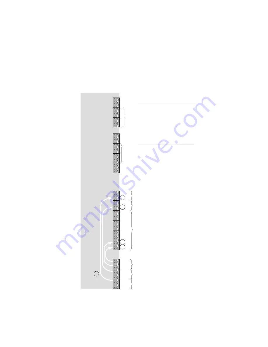
The MDF Connection Unit provides access to the Main Equipment ports via screw-terminals. These
screw terminals have been arranged so as to provide:
Separation between exchange lines and internal equipment.
Access to extension ports.
Access to the Door Phones, Paging port, Alarm Loops and Terminal signalling ports.
Extensions 14, 21 and 23 are suitable for external wiring and is fitted with the required protection
circuitry.
Figure 4-4 shows the terminal layout.
Figure 4-4 MDF connections – 208 system
Po
w
er
fail
co
nn
ec
ti
on
s
(PS
T
N
o
nl
y)
Paging port
Door phone 2
Not used
2
1
Door phone 1
Door 1 latch relay
24
23
22
21
18
17
16
15
14
13
12
11
1
2
3
4
5
6
Terminal Signalling (4 pairs in parallel)
Dr
R
ly_
Dr
1v
C
O
4__C
O3
-T
x+
-Rx+
C
O
2__C
O1
Pf
ai
l
P
fai
l
Ex
t1
1_E
xt
12
Ex
t13_E
xt
14
Ex
t15_E
xt
16
Ex
t17_E
xt
18
Pfa
il
Ex
t21_E
xt
22
P
fa
il
Ex
t23_E
xt
24
C
O
6__C
O5
-T
x+
-Rx+
Te
rS
ig1_S
ig2 A
ux
Si
g1_S
ig2
D
r2v
_P
age
Al
m
1_A
lm
2
Al
m
3_A
lm
4
Alm
R
ly
C N
C
C N
O
Ex
te
ns
io
ns
M
is
cel
la
neo
us
Ex
cha
ng
e L
in
es
Al
arms
Alarm Loops (3 & 4 factory option only)
Expansion slot 1
Expansion slot 2
Basic system
Expansion slot 2 ISDN or PSTN
Expansion slot 1 ISDN or PSTN
Basic system
4


