background image


25 


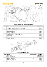
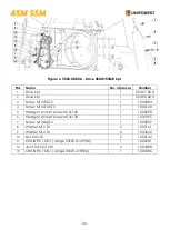
Figure 4: 5002.08.00.0 

 Drive 45M/55M kpl. 


Figure 5: 502.08.00.0 

 Drive. 


Pos.


Name


No. of pieces


Number


Drive kpl. 

502.08.00.0 

CHAIN RK 16 B-1 (Lange 57x25,4=1447,8) 

1000292 

Joint link SG 16 B1 

1003488 

Screw M12x65 Zn 

1000045 

Screw M12x95 Zn 

1000047 

Hexagon socket screw M12x120 

1001095 

Nut M12 Zn 

1000142 

Washer M12 Zn 

1003632 

Washer M12 Zn 

1000161 

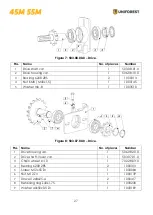
Pos.


Name


No. of pieces


Number


Drive shaft 

502.08.02.A 

Drive housing var. 

502.08.10.0 

Bearing 6208 2RS 

1000313 

Nut KM8 ( M40x1,5) 

1000145 

Washer mb-8 

1003510 

Summary of Contents for 45M

Page 1: ...ORESTRY WINCH 45M MR 55M MR Spare parts list THE MANUFACTURER Uniforest d o o Latkova vas 81d 3312 Prebold www uniforest si Valid from serial number 45M 11108000514 45MR 11208000360 55M 11310000669 55...

Page 2: ...d you to carefully read the user manual In case of doubt do not hesitate to contact us We wish you safe work with the machine 1 Index GENERAL 2 1 Index 2 2 Intended use 3 3 Technical data 3 SAFETY INS...

Page 3: ...egulations on technical safety of devices health regulations and road rules must be observed The manufacturer is not liable for any damages that may arise from users making unauthorized changes on the...

Page 4: ...c Pulling force at the internal diameter of the drum Pulling force at the external diameter of the drum Operating pressure Wire rope length Min breaking force Specific min breaking force Max PTO shaf...

Page 5: ...should be removed by an expert Before first use or after significant alterations and at least once a year the winch must be examined by an expert 6 When using public transport routes observe traffic s...

Page 6: ...replaced immediately 22 It it necessary to use a wire rope of an appropriate lenght When you wind the rope up a distance of 1 5 of rope diameter to outer diameter of the drum should stay on the drum...

Page 7: ...eed to choose an appropriate hard and flat surface Fix the winch by means of support legs Lean the drive shaft on the prepared holder 33 In the area of the three point linkage there is a danger of inj...

Page 8: ...size of the load to the tractor s power capacity You should also pay attention to the inclination of the slope and the terrain to avoid a rollover and to maintain a safe steering and braking performa...

Page 9: ...stopped and the ignition key has been removed 5 The cardan shaft must always be properly mounted and protected 6 Secure the cardan shaft agains rotating with a chain 7 Before switching on the cardan s...

Page 10: ...volutions and direction of tractor PTO shaft rotation is 540 min 1 3 Pto shaft adjustment Length of PTO shaft needs to be adjusted for different tractors gure F1 F4 For winch 45M MR 55M MR the use of...

Page 11: ...nnection points Once the winch is attached to the tractor strengthen the stabilizers on the lower connection rods and level the winch with a hitch nut into position so that the winch is tilted backwar...

Page 12: ...Towing Figure 9 Lower the winch on the ground so that the winch is supported by a hard surface Engage the hand brake Never start towing if a winch is not in a stable position on the ground Before you...

Page 13: ...tion surface of the clutch has been reduced too much The winch will not be able to reach to necessary traction force and the friction surface of the clutch will be damaged due to sliding 2 Safety brak...

Page 14: ...to the left in order to tighten the brake belt and vice versa For optimal operation the gap between the nuts must be 11 mm If the brake force is not suf cient repeat the procedure and tighten the nut...

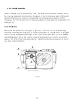
Page 15: ...move the protective sheet of the PTO shaft pos 1 Series M winches First loosen the nut and the screw pos 2 gure 13 which are used to x the housing Then start tensioning the chain pos 3 with the screw...

Page 16: ...e tensioning screw pos 3 to the left This prevents the gap between both housings Finally tighten the lock nut pos 2 and the retaining screws of the upper housing pos 7 Figure 13 5 Wire rope assembly F...

Page 17: ...it with spray for lubrication of chains or special grease which does not melt at high temperatures because the grease can come into contact with friction coating of the clutch First remove the cardan...

Page 18: ...ting Set according to instructions cannot be for use unreeled or the unreeling is dif cult Incorrect brake settings Set according to instructions for use Damaged or stuck wire rope Unreel the rope wit...

Page 19: ...lutch friction Replace the clutch coating The drive chain is too tense Set drive chain according to instructions for use Winch is very loud The drive chain is not tense Set drive chain according durin...

Page 20: ...DEVICE MACHINE WINCH UNIFOREST 45M 45MR 55M 55MR WE DECLARE UNDER OUR SOLE RESPONSIBILITY THAT THE ABOVE MENTIONED MACHINE WINCH UNIFOREST 45M 45MR 55M 55MR IS COMPLIANT WITH THE FOLLOWING REGULATION...

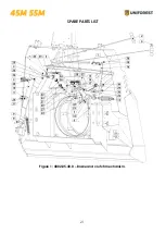
Page 21: ...21 SPARE PARTS LIST Figure 1 4002 05 30 0 Brake and clutch mechanism...

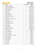
Page 22: ...r link 2 5002 05 43 0 15 Compression spring 1 5002 05 63 0 16 Brake lever var 1 5002 05 45 0 17 Automation system kpl 1 5002 05 50 c 18 Clutch plate 1 5006 05 11 0 19 Clutch plate 1 5006 05 12 0 20 Pr...

Page 23: ...Fork eye 1 5006 05 16 0 2 Brake tube 1 5002 05 22 0 3 Spring washer 1 5002 05 23 0 4 Brake bush 1 5002 05 24 0 5 Brake spring 1 5002 05 40 0 6 Bolt 1 5006 05 14 0 7 Screw M12x220 Zn 1 1000122 8 Nut M...

Page 24: ...6 01 0 3 Drum shaft var 1 5006 06 06 0 4 Clutch plate 240 1 5006 06 09 0 5 Clutch plate 274 1 5006 06 10 0 6 Distance bush 1 5006 06 14 0 7 Bearing 6308 ZZ 3 1000303 8 Bearing 6208 2Z 2 1000301 9 DISC...

Page 25: ...Joint link SG 16 B1 1 1003488 4 Screw M12x65 Zn 1 1000045 5 Screw M12x95 Zn 1 1000047 6 Hexagon socket screw M12x120 1 1001095 7 Nut M12 Zn 3 1000142 8 Washer M12 Zn 2 1003632 9 Washer M12 Zn 2 10001...

Page 26: ...084 4 Screw M12x100 Zn 1 1000120 5 Hexagon socket screw M12x100 1 1000098 6 Hexagon socket screw M12x120 1 1001095 7 Screw M12x40 Zn 1 1000059 8 Washer M12 Zn 2 1000161 9 Washer M12 Zn 4 1003632 10 Nu...

Page 27: ...2 1000313 4 Nut KM8 M40x1 5 1 1000145 5 Washer mb 8 1 1003510 Pos Name No of pieces Number 1 Drive housing var 1 506 08 20 0 2 Drive shaft lower var 1 503 07 01 0 3 Chain wheel z 10 1 702 28 03 0 4 Be...

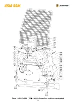
Page 28: ...28 Figure 9 4002 13 00 0 5002 13 00 0 Protections and mechanisms kpl...

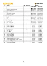
Page 29: ...10 Screen var 1 5008 88 00 0 5008 88 00 0 11 Bolt lower var 2 502 00 20 0 502 00 20 0 12 Upper tractor bolt Zn 1 502 00 15 0 502 00 15 0 13 Screw M8x16 Zn 3 1000050 1000050 14 Screw M10x70 Zn 2 101083...

Page 30: ...0 Figure 10 5002 00 60 0 PTO protection Pos Name No of pieces Number 1 PTO protection 1 5002 00 61 0 2 PTO protection 1 305 35 02 0 3 Screw M8x16 Zn 4 1000050 4 Washer M8 Zn 4 1003465 5 Rivet 3 100368...

Page 31: ...plate var 1 5002 11 05 0 2 PTO bracket Zn 1 502 11 08 0 3 Small cover 1 502 11 09 0 4 Screw M8x16 Zn 1 1000050 5 Screw M12x55 Zn 1 1000084 6 Screw M12x20 Zn 4 1000055 7 Nut M12 Zn 1 1000139 8 Washer...

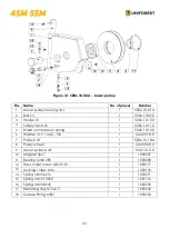
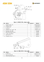
Page 32: ...6 10 12 0 6 Washer 31 9 44 5 5 8 1 502 09 18 0 7 Pulley bolt 1 5006 10 18 A 8 Pulley wheel 1 502 09 08 0 9 Lower pulley bolt 1 502 10 10 0 10 Magnet 36x7 1 1000507 11 Bearing 6306 2RS 1 1000308 12 Hex...

Page 33: ...08 0 3 Pulley bush 1 502 09 09 0 4 Spacer 1 1 502 09 17 0 5 Washer 31 9 44 5 5 8 1 502 09 18 0 6 Bearing 6306 2RS 1 1000308 7 Retaining ring N72x2 5 1 1000236 8 Screw M12x80 Zn 1 1000046 9 Nut M12 Zn...

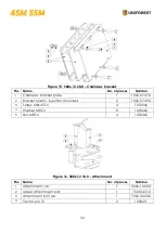
Page 34: ...bracket plate 1 1020 07 47 0 2 Bracket plastic injection moulded 2 1020 07 49 0 3 Screw M8x45 Zn 4 1012046 4 Washer M8 Zn 8 1003465 5 Nut M8 Zn 4 1003460 Pos Name No of pieces Number 1 Attachment var...

Reviews: