background image


SAS to SAS/SATA JBOD Subsystem


18 

User Manual 


2.2   Disk Drive Installation 


This section describes the physical locations of the hard drives supported by the 
subsystem  and  give  instructions  on  installing  a  hard  drive.  The  subsystem 
supports hot-swapping allowing you to install or replace a hard drive while the 
subsystem is running. 


2.2.1   Installing 3.5” SAS Disk Drive in a Disk Tray 


1.


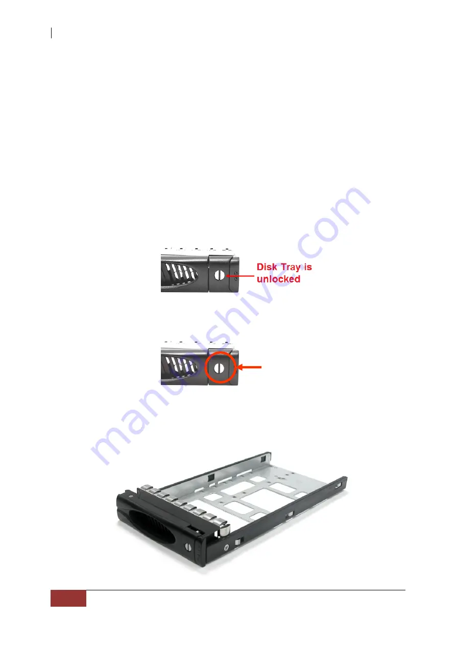
Unlock  the  Disk  Trays  using  a  flat-head  screw  driver  by  rotating  the  Lock 
Groove. 


2.


Press the Tray Open button and the Disk Tray handle will flip open. 


3.


Pull out an empty disk tray.  


Tray      

Open  
Button 

Summary of Contents for Proware EP-3166J1/JD1-SCSC

Page 1: ...SAS to SAS SATA JBOD Subsystem User Manual Revision 1 1...

Page 2: ...D 12 1 6 2 LCD Panel Function Buttons 13 1 6 3 Menu Diagram 14 1 7 Drive Carrier Module 15 1 7 1 Disk Drive Status Indicators 15 1 7 2 Drive Carrier Lock Indicator 16 Chapter 2 Installation of JBOD Su...

Page 3: ...latest enhancements in SAS along with LSI DataBolt bandwidth optimizer technology EDFB End Device Frame Buffering Using DataBolt it delivers optimized throughput by allowing users to gain 12Gb s host...

Page 4: ...h optimizer technology Power Supply Power supply and cooling system contained in 1 module for efficient cooling Two 500W redundant hot swappable power supplies Enclosure Incorporates a cableless desig...

Page 5: ...ount Form Factor 3U of Hot Swap Trays 16 Disk Status Indicator Access Fail LED Backplane SAS SATA Single BP of PS Fan Modules 500W x 2 w PFC of Fans 4 Power requirements AC 90V 264V Full Range 10A 5A...

Page 6: ...serial cables for dual JBOD controllers One 1 mini SAS HD cable for single JBOD controller Two 2 mini SAS HD cables for dual JBOD controllers One 1 Ethernet LAN cable for single JBOD controller Two 2...

Page 7: ...S SATA JBOD Subsystem User Manual 7 1 4 Identifying Parts of the Expansion Chassis The illustrations below identify the various parts of the expansion chassis 1 4 1 Front View Drive Carriers LCD Displ...

Page 8: ...SAS to SAS SATA JBOD Subsystem 8 User Manual 1 4 2 Rear View Single Controller Dual Controller...

Page 9: ...LED SAS IN and SAS OUT Green indicates SAS IN OUT Port has connected or linked Access LED SAS IN and SAS OUT Blue indicates SAS IN OUT Port is being accessed RS 232 Port Used for upgrading the Firmwa...

Page 10: ...is 1 5 1 PSFM Panel The Power Supply Fan Module panel has Power On Off Switch the AC Inlet Plug and a Power On Fail Indicator showing the Power Status LED indicating ready or fail Each fan within a PS...

Page 11: ...en the Power On Fail LED is GREEN the PSFM is functioning normally 1 5 3 Fans of PSFM Each PSFM has 2 fans Master Fan and Slave Fan The Master Fan is located beside the PSFM panel The Slave Fan is loc...

Page 12: ...l turn to RED and alarm will sound Fan Fail LED Turn RED when fan 1 or 2 fails or speed is lower than 3000 RPM for Master Fan and 2500 RPM for Slave Fan Over Temperature LED If system temperature is o...

Page 13: ...s also used to move between each menu Select button This is used to enter the option you have selected Exit button EXIT Press this button to return to the previous menu NOTE This button can also be us...

Page 14: ...x Temperature Enclosure 30 C Chip 35 C HDD01 33 C HDD16 30 C Power Status Power01 Good Good Power02 Good FAN Status Fan01 3970 rpm Good Fan03 3970 rpm Fan02 3970 rpm Fan04 3970 rpm Voltage Status 3 3V...

Page 15: ...has 2 status indicator lights One indicator light is used for Power On Error When this light is GREEN the power is on and everything is functioning normally When the Power On Error light is RED then...

Page 16: ...er is locked into the chassis or not Each carrier is also fitted with an ergonomic handle for easy carrier removal When the Lock Groove is vertical then the Drive Carrier is unlocked When the Lock Gro...

Page 17: ...into the AC Power Input Socket located at the rear of the subsystem NOTE The subsystem is equipped with redundant full range power supplies with PFC power factor correction The system will automatical...

Page 18: ...installing a hard drive The subsystem supports hot swapping allowing you to install or replace a hard drive while the subsystem is running 2 2 1 Installing 3 5 SAS Disk Drive in a Disk Tray 1 Unlock...

Page 19: ...A of the disk tray To secure the disk drive into the disk tray tighten four screws on these holes of the disk tray Note in the picture below where the screws should be placed in the disk tray holes N...

Page 20: ...ray into a slot 6 Press the lever in until you hear the latch click into place The HDD Fault LED will turn green when the subsystem is powered on and HDD is good 7 If necessary lock the Disk Tray by t...

Page 21: ...stem 2 Place the disk drive in the disk tray Turn the disk tray upside down Align the four screw holes of the disk drive in the four Hole w of the disk tray To secure the disk drive into the disk tray...

Page 22: ...al NOTE All the disk tray holes are labelled accordingly 3 Slide the tray into a slot 4 Press the lever in until you hear the latch click into place The HDD Fault LED will turn green when the subsyste...

Page 23: ...ling 3 5 SATA Disk Drive Dual Controller Mode in a Disk Tray 1 Remove an empty disk tray from the subsystem 2 Prepare the dongle board the Fixed Bracket and screws Fixed Bracket Dongle Board Screws 3...

Page 24: ...SAS to SAS SATA JBOD Subsystem 24 User Manual 4 Place the Fixed Bracket with the dongle board in the disk tray as shown...

Page 25: ...oles of the Fixed Bracket in the two Hole d of the disk tray Tighten two screws to secure the Fixed Bracket into the disk tray NOTE All the disk tray holes are labelled accordingly 6 Place the SATA di...

Page 26: ...ray Note in the picture below where the screws should be placed in the disk tray holes NOTE The mounting hole locations of the new 6 disk are different from the existing drives 3 4 and 5 disk 6 disk F...

Page 27: ...ling 2 5 SATA Disk Drive Dual Controller Mode in a Disk Tray 1 Remove an empty disk tray from the subsystem 2 Prepare the dongle board the Fixed Bracket and screws Fixed Bracket Dongle Board Screws 3...

Page 28: ...SAS to SAS SATA JBOD Subsystem 28 User Manual 4 Place the Fixed Bracket with the dongle board in the disk tray as shown...

Page 29: ...es of the Fixed Bracket in the two Hole d of the disk tray Tighten two screws to secure the Fixed Bracket into the disk tray NOTE All the disk tray holes are labelled accordingly 6 Place the 2 5 SATA...

Page 30: ...rive in the four Hole y of the disk tray To secure the disk drive into the disk tray tighten four screws on these holes of the disk tray Note in the picture below where the screws should be placed in...

Page 31: ...A external SAS connector or to the SAS Switch The host bus adapter is installed in your Host computer system 2 3 2 Connecting to RAID Subsystem Attach one end of the SAS cable to the SAS IN Port of th...

Page 32: ...E Upgrading the firmware must be done from Master JBOD Controller JBOD Controller 1 if the JBOD Subsystem has redundant JBOD Controllers Steps 1 Please use the RS232 cable RJ 11 to DB9 to JBOD Control...

Page 33: ...SAS SATA JBOD Subsystem User Manual 33 4 Select Transfer Send File You must finish within 25 seconds 5 Select your firmware file path and select Xmodem in the communication protocol and click transfer...

Page 34: ...SAS to SAS SATA JBOD Subsystem 34 User Manual 6 Wait for the transfer of file to complete...

Page 35: ...AS to SAS SATA JBOD Subsystem User Manual 35 7 When the transfer and firmware update is complete please power cycle the JBOD 8 In command line type system info you can see the Expander firmware versio...

Reviews: