background image

14 

2.4 Password 

2.4.1 

Access to service levels by password 

Depending on password (service or OEM), different parameters are visible.  
"Service" parameters, as per the actuator curves and the set-point values, are password protected. The operator must logon using the "

9876

" password. 

"User" level doesn't need a password. 
If a password shall be entered, line Enter password is selected by means of decrementing (pointer points to the first character of that line) and then 
finally selected by pressing Enter. 
Then, the pointer jumps to the first position of the password entry line. Now, through incrementing or decrementing, a character (digit or letter) can be 
selected. A character is confirmed by pressing Enter. If a wrong entry has been made, the last character can be edited again by pressing Esc. 
The other password positions can be selected, edited and entered in a similar way. Hence, when making an entry, only 1 character is visible. When the 
last character of the password is reached, the entry is to be confirmed by pressing Enter. 
 
Display before the first password character is entered: 

Enter Password 


* * * * * * * *          

 
The example displays when entering the third password character: 

Enter Password 


* * 

* * * * *          

 
If the check of the password entered is positive, the change to the next menu level takes place. Otherwise, the display returns to the main menu level. 
To go back to the main menu, press “Esc”            until the first level menu is reached, then press the “right arrow”    , un   till the first item is reached, 
then press “ Enter “   twice. 
 

2.4.2 Password 

Logout 

To avoid customer changes on parameter settings and consequently changes in regulation, the password must be logged out. The  “password logout” 
functions on the first level menu: press   to choose “PW Logout”  then press “Enter“. 
 

Note: 

if no key is pressed within a settable period, the password is deactivated automatically. 

Note: 

if a power supply drop occurs to the unit, the password will be automatically deactivated. 


2.4.3 Changing 

password. 

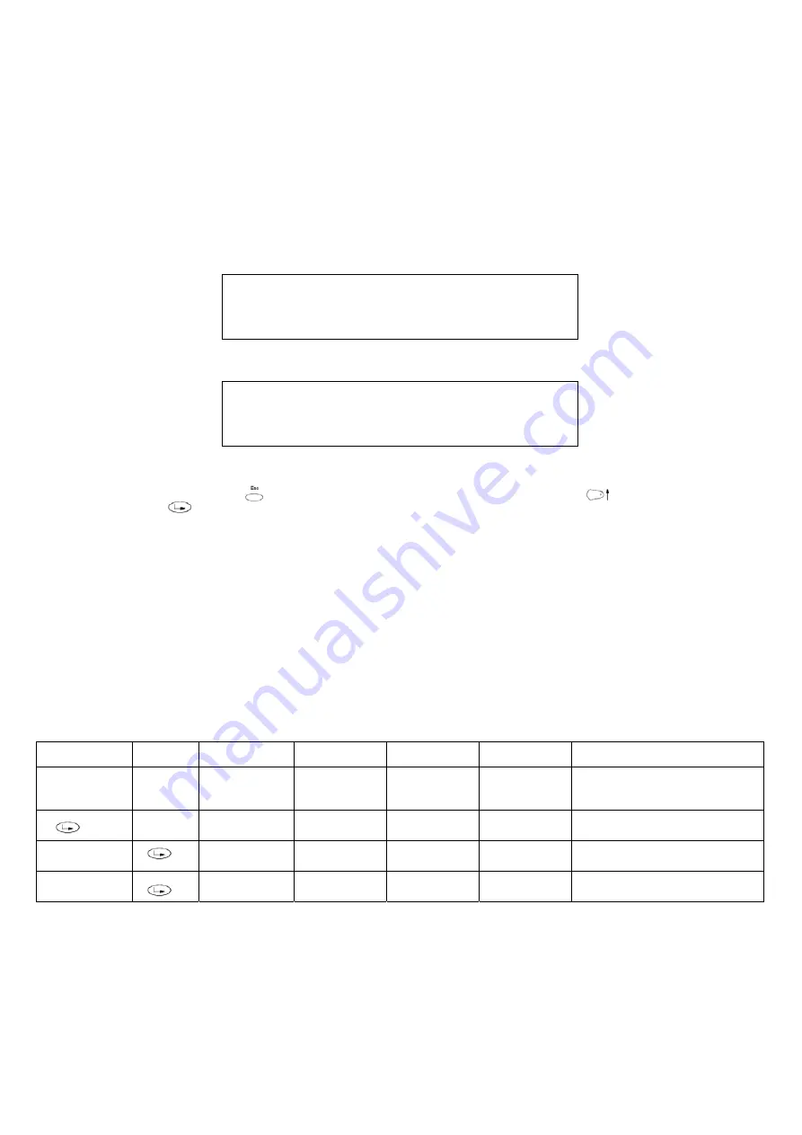
Following the below route access to the programming levels of the menu by means the Esc  
 

1st level 

2nd level 

3rd level 

4th level 

5th level 

6th level 

Description 

Updating 


  Password 

     To 

change 

password 


ServicePassword 

   For 

service 

only 


OEM Password 


For OEM only 


Summary of Contents for E115X

Page 1: ...M039622CA 0 1 11 2022 BURNERS BRUCIATORI BRULERS BRENNER QUEMADORES MANUAL OF INSTALLATION USE MAINTENANCE E115X E150X E180X Microprocessor controlled LMV 5x Gas burners...

Page 2: ...non original components whether spare parts kits accessories and optionals Force majeure Furthermore the manufacturer declines all responsibility for non compliance with this manual Personnel training...

Page 3: ...rner shut down reser the control box by means of the RESET pushbutton If a second shut down takes place call the Tech nical Service without trying to RESET further The unit shall be operated and servi...

Page 4: ...UNI EN ISO 12100 2010 Safety of machinery General principles for design Risk assessment and risk reduction For the following information please refer to the data plate Burner type and burner model mu...

Page 5: ...s according to load curves in order to achieve the correct proportion between fuel and air flows and to optimize flue gas parameters The adjustable combustion head can improve the burner performance b...

Page 6: ...andard blast tube aluminium air intake LR Extended blast tube ABS polymer silenced air intake LP Extended blast tube aluminium air intake 5 DESTINATION COUNTRY see data plate 6 BURNER VERSION A Standa...

Page 7: ...rific value Hi 93 5 MJ Stm3 Note2 Maximum gas pressure 360 mbar with Dungs MBDLE 500 mbar with Siemens VGD or Dungs MultiBloc MBE Minimum gas pressure see gas curves Note3 Burners are suitable only fo...

Page 8: ...e On this diagram the maximum output point is usually reached by adjsuting the combustion head to its MAX position see paragraph Adjusting the combustion head the minimum output point is reached setti...

Page 9: ...es natural gas WARNING the diagrams refers to natural gas For different type of fuel please refer to the paragraph Fuel at the beginning of this chapter GAS PRESSURE IN THE NETWORK mbar E115X M Gas ra...

Page 10: ...pressure burner head vs natural gas flow rate Curves are referred to pressure 0 mbar in the combustion chamber Gas pressure in combustion head mbar E115X M Stm3 h E150X M Stm3 h Gas pressure in combus...

Page 11: ...593 292 80 1054 692 558 428 565 310 E150X 40 1192 1258 400 500 996 634 259 280 457 327 541 50 472 342 526 65 1080 718 562 432 593 292 80 1054 692 562 432 565 310 E180X 40 1292 403 996 634 235 457 327...

Page 12: ...ust be done in accordance with current local regu lations PS PSH PSL PSL PSH PS M M con valvole MB DLE con valvole VGD con valvole MBE gas inlet gas inlet gas inlet Legend 1 Filter 2 Low pressure swit...

Page 13: ...ual Example Furnace input 600kW Backpressure 4 mbar In the Performance curve diagram draw a vertical line matching the fur nace input value and an horizontal line matching the backpressure value The b...

Page 14: ...or handling operations and it can be lifted with a hydraulic lift or a small manual crane A The burner is mounted on a stirrup provided for handling the burner by means of a fork lift truck the forks...

Page 15: ...fasten the 4 stud bolts place the ceramic fibre plait on the burner flange install the burner into the boiler fix the burner to the stud bolts by means of the fixing nuts according to the next pictur...

Page 16: ...he pressure in combustion chamber are included in the burner performance curve otherwise the choice of the burner must be revised consulting the burner manufacturer To choose the blast tube lenght con...

Page 17: ...of gas flow must follow the arrow on the body of the components mounted on the gas ramp valves filters gaskets NOTE the bellows unit the manual cutoff valve and the gaskets are not part of the standa...

Page 18: ...p and pressure switches plugs MultiBloc MB DLE Assembling the gas train ATTENTION it is reccomended to install the filter with gas flow parallel to the floor in order to prevent dust fall on the safet...

Page 19: ...GMAX pressostato gas di massima 5 Azionatore con stabilizzatore di pressione incorpo rato 6 Azionatore On Off 7 Corpo valvola Filettata 8 Corpo valvola Flangiata Nelle versioni apparecchiatura Facile...

Page 20: ...2 built in pressure stabilizer Siemens VGD VRD SKPx5 Auxiliary optional micro switch Gas valve Se necessario il microinterruttore ausiliario POC deve essere ordinato un attuatore dedicato diverso da q...

Page 21: ...21 Siemens VGD Pressure taps G 1 4 G 1 8 G 1 4 G 3 4 G 1 8 G 1 4 G 1 8 Strainer 1 9 3 4 5 2 11 7 6 8 2 V 1 V 10 1 2 4 3 9 1 6 10 3 2 11 10 5 6 7 8 9 Legenda pi Inlet pressure pm Pressure between val v...

Page 22: ...with fan motor driven by inverter in addition to the air and fuel adjustment curves also have a fan motor speed adjustment curve Generally the curve of the inverter goes from 50 to 100 of the engine...

Page 23: ...trol box please refer to the clabeling recommendations avaible on the Siemens CD attached to the burner WARNING Respect the basic safety rules make sure of the connection to the earthing system do not...

Page 24: ...DEPARTS FROM THE INSTALLATION OPERATIONS OR WHICH HAPPENS AFTER TOTAL OR PARTIAL TAMPERING WITH THESE E G DISCONNECTION EVEN PARTIAL OF THE ELECTRICAL LEADS OPENING THE GENERATOR DOOR DISMANTLING OF...

Page 25: ...burner staring cycle begins in case of leakage in a valve the gas proving system stops the bur ner and the lamp B1 turns on At the beginning of the start up cycle the actuator drives the air damper to...

Page 26: ...td1 The pressure switch PGCP has not to detect a rise of pressure Test space filling EV1 opens and keep this position for a preset time td3 in order to fill the test space Test gas pressure EV1 close...

Page 27: ...correct 9 Open the manual shut off valves slowly in order to prevent any water hammers that might seriously damage valves and pressure regulator 10 Check the sense of rotation of the electrical motor...

Page 28: ...e second page Second page Fuel it shows in degrees the fuel actuator position Air it shows in degrees the air actuator position Ax1 3 auxiliaries VSD value on the inverter maximum frequency O2 oxygen...

Page 29: ...he Fault History pages press ESC Lockout History To visualise the Lockout History choose the related item and press ENTER The message will be alternating by an error message as To see the other Lockou...

Page 30: ...he unit measure of the detected value and its limits are bound up with parameters set at the Service level Once the new set point is set confirm by pressing ENTER otherwise exit without changings by p...

Page 31: ...turn off at a temperature 1 higher than the set point Change value if needed by means of the arrow keys press ENTER to confirm and the press ESC to exit Press only ESC to exit without changing Press t...

Page 32: ...it choose the temperature and pressure unit and cofirm by pressing ENTER press ESC to exit System lockout If the system locks out the following message will appear call the Technical Service and tell...

Page 33: ...Autom Manual Off three modes are provided Automatic automatic operation Burner on manual operation Burner off burner in stand by If the BurnerOn mode is choosen the burner does not follow the modulato...

Page 34: ...he minimum gas pressure switch Slowly close the manual cutoff valve placed upstream the pressure switch see gas train installation diagram until the detected pressure is reduced by 50 Pay attention th...

Page 35: ...n reduces start flow rate anticlockwise rotation increases it Do not use a screwdriver on the screw VR The pressure stabilizer is adjusted by operating the screw VS located under the cover C By screwi...

Page 36: ...er increase the regulation pressure by slowly turning the control knob clockwise until the burner stops taking care it does not go into lockout and the display shows the error Err c20 d0 As for the ga...

Page 37: ...he position loosen the VB screw and slightly move the combustion head backwards turning clockwise the knob VRT Fasten VB screw when the adjustment is accomplished Depending on the boiler application i...

Page 38: ...cific maintenance is needed In case of anomalous noises when running check the condition of the bearings and eventually substitute them or completely substitute the motor Clean and examine the gas fil...

Page 39: ...gas supply closing the on off valve 2 Remove screws 1 4 using the Allen key n 3 and remove filter cover 5 in Fig 5 3 Remove the filter 6 and replace with a new one 4 Replace filter cover 5 and tighten...

Page 40: ...1 2 3 4 5 6 7 1 Position VD on VB fig 2 3 2 Slide VD forward up to the stop fig 4 3 Screw VD on with 2 M5 screws for each max 5 Nm 44 in lb fig 5 6 4 VD can be mounted rotated by 180 fig 7 VB VD SKP1...

Page 41: ...ter any intervention on the combustion head Remove the lid C Unscrew the screws V holding in position the manifold G and pull out the complete group as shown in figure Note for the subsequent assembly...

Page 42: ...Minimum detection signal Siemens LMV2x 3x Ionization probe 3 A values on display 30 0 1 2 3 4 5 6 7 35 34 33 32 31 30 8 15 14 9 10 11 12 13 17 18 19 20 16 21 22 23 24 25 26 28 29 27 A A B B C C D D E...

Page 43: ...ts or a decrease in performance The owner makes the decision whether to finish using the burner or replacing and disposing of it based on the actual state of the appliance and any repair costs The use...

Page 44: ...itch functions and links Burner control damaged Replace burner control BURNER LOCKS OUT WITHOUT ANY GAS FLOW Gas valves don t open Check voltage on valves if necessary replace valve or the burner cont...

Page 45: ......

Page 46: ......

Page 47: ......

Page 48: ...a L Galvani 9 35011 Campodarsego PD ITALY Tel 39 049 9200944 Fax 39 049 9200945 9201269 web site www cibunigas it e mail cibunigas cibunigas it Note specifications and data subject to change Errors an...

Page 49: ...Siemens LMV5x Service Manual M12920CC rev 2 1 08 2017...

Page 50: ...harmful Before any cleaning or servicing operation disconnect the unit from the mains by turning the master switch OFF and or through the cut out devices that are provided Make sure that inlet or exh...

Page 51: ...2 Configuration of a pressure or a temperature probe type at X61 door 20 6 2 1 Configuration of a pressure or a temperature probe signal at X61 door 20 6 3 Configuration of the X62 door input signal...

Page 52: ...must be connected to earth PE Volt must be 0 V between N PE NOTE PE protection earth it is not FE FE functional earth 1 1 2 Protective Earth PE and Functional Earth FE Protective Earth PE Known as an...

Page 53: ...les and to the burner housing e g use a electrical insulating conduit or distance parts e g plastic material see also Appendix Example for wiring earthing and shielding the LMV5 System Prefer a double...

Page 54: ...lso Appendix Example for wiring earthing and shielding the LMV5 System 1 3 2 Shielding The LMV5 FE terminals for the shields are LMV5 internally connected with X52 4 this terminal must be connect exte...

Page 55: ...ables for the Load controller Temperature or Pressure sensor set point load output at the LMV5 X60 X61 X62 X63 Together in cable duct 2 for Line voltage e g Cable for Ignition transformer Cables for o...

Page 56: ...8...

Page 57: ...9 1 4 1 Servomotor wiring example 1 4 2 Bus cable wiring on LMV5x and AZL doors 1 4 3 EARTH connection example...

Page 58: ...urner will immediately turns off keys socket The user interface is made of display it shows menus and parameters ESC key previous level it goes back to the previous level menu or exits the programming...

Page 59: ...ition position phase 38 The burner remains in that position because this is the only one work point in memory The fuel air ratio curve must be set until the maximum load limit 100 output During the se...

Page 60: ...12 2 2 LMV5x program structure...

Page 61: ...ED TO NOT USE O2 MONITORING IF FGR IS INSTALLED AND ACTIVE 2 3 Burner ID number The burner ID number corresponds to the burner serial number NOTE in case of call to the Service Center always tell the...

Page 62: ...rmed by pressing Enter Display before the first password character is entered Enter Password The example displays when entering the third password character Enter Password S If the check of the passwo...

Page 63: ...nals 318 and 319 of the burner supply terminal block see below the system will lead to an immediate burner lockout In case of burner designed with automatic pull out system from the generator the burn...

Page 64: ...address an actuator choose the corresponding actuator and follow the instructions on display When the actuator green LED flashes it means that one of the following function is set according to the nu...

Page 65: ...o according to the next procedure By following the next table set both parameter OperatRampMod and TimeNoFlame to set the ramp up stop times for the VSD and the actuator opening speed from 0 to 90 Fol...

Page 66: ...al output from the LMV to the client DCS or PLC Output Value Selection are Load Load 0 O2 Pos Air Pos Fuel Pos Aux1 Pos Aux2 Pos Aux3 Speed VSD Flame Temp Pt1000 TempNi1000 Temp Pt100 Temp X61 Press X...

Page 67: ...level 5th level 6th level Description Params Display Menu level for making the parameter set tings LoadController Settings for the internal load controller Configuration General configuration of the l...

Page 68: ...ens End of pressure measuring range for input X61 0 99 9 bar 0 2000 C 0 99 9 bar 0 2000 C Set the probe value Example if a max 10bar Siemens sensor is used the voltage output signal will be 0 V at 0 b...

Page 69: ...6th level Description Params Display Menu level for making the t Params Display SD ModOn General configuration of the load SD ModOn SD ModOff General configuration of SD ModOff the display will show T...

Page 70: ...for internal load controller StandardParam Adaption very fast fast normal slow very slow It is possible to manually set the PID parameters to any value in the setting range shown below to activate a...

Page 71: ...100 Ni1000 or Pt 1000 temperature sensor is connected to X60 3 and X60 4 terminals ATTENTION basically these parameters provide a function similar to the safety thermostat one but can not replace it T...

Page 72: ...of the menu by means the Esc 1st level 2nd level 3rd level 4th level 5th level Range Description Params Display Menu level for making the parameter settings VSD Module Settings for the VSD module Conf...

Page 73: ...ogramming levels of the menu by means the Esc 1st level 2nd level 3rd level 4th level 5th level 6th level Description Params Display Menu level for making the para meter set tings RatioControl GasSett...

Page 74: ...corresponding to a hypothetic low flame stage Note points P1 and P2 are temporally mentioned 10 and 100 load independently from the actual load The operator can name the load on each point without re...

Page 75: ...of oil ATTENTION as for increasing by few degrees it means that the increasing must be performed in order to avoid great excess of air or defect of air Therefore the increasing operation must be perfo...

Page 76: ...ir actuator Do not exit by pressing Esc from the values column because data will not be stored Press arrows to select another actuator to be set for example press to choose Fuel Press keys to change t...

Page 77: ...the other points So it is necessary to check the adjustment of the points already set ATTENTION for proper operation it is necessary that the curve of each actuator does not reverse its slope ATTENTI...

Page 78: ...cts are the following 1 Pressures have reciprocal effects 2 The reduction of O2 can lead to a significant increase of NOx levels As a result of these reciprocal effects it is difficult if not impossib...

Page 79: ...ngs for firing on Gas or on Oil AirActuator GasActuat OilActuat AuxActuator AuxActuator 2 AuxActuator 3 AuxActuator 3 AuxActuator 3 MUST be chosen After the addressing activate the FGR servomotor 1st...

Page 80: ...Open 10 4 Setting the load controller mode see the previous chapter regolazione senza FGR WARNING If one of the intLC internal Load Controller option must be choice a temperature sensor cannot be con...

Page 81: ...ulation temperature Auxiliary actuator 3 maintains the ignition position until an adjustable temperature is reached parameter FRG On Temp During the operation the burner regulate its load as per the s...

Page 82: ...inimum amount of flue gas The position is also used to ensure a defined damper position for emergency operation or automatically deactivated flue gas recirculation FGR FGR MaxPos Fact Maximum limitati...

Page 83: ...on FGR factor of 50 leads to a 50 reduction of the damper positions If the temperature value of the smoke during the operation of the burner is higher than the temperature value during the commissioni...

Page 84: ...StageLoad 0 100 15 StageSetp_M od 1 100 Wcurrent 5 Stage Setp_Stage 1 100 Wcurrent 5 MaxTme Mod 1 63 min 3 min MaxTmeStage 1 63 min 3 min Cold start thermal shock protection maximum time per step mult...

Page 85: ...tion this function can be set at user level also see chapter manual operation the CSTP function is momentary excluded when enabling the automatic operation again the CSTP function previously set at Se...

Page 86: ...assword Description ManualOpe ration Menu level for activating manual operation with the preselected load Au tom Manual Off Selection of manual or automatic operation Automatic Burner on Burner off Us...

Page 87: ...39...

Page 88: ...V 10 15 50 60 Hz Imax 5 A PIN3 x Protective earth PE PIN4 x Supply voltage neutral conductor N PIN5 x Supply voltage live conductor L AC 230 V 10 15 50 60 Hz fuse 6 3 AT DIN EN 60 127 2 5 X4 01 Fuel s...

Page 89: ...5 mA PIN2 x Controller closes stage 3 AC 230 V 10 15 50 60 Hz Imax 1 5 mA PIN3 x Controller opens stage 2 AC 230 V 10 15 50 60 Hz Imax 1 5 mA PIN4 x Power signal for control of con troller AC 230 V 10...

Page 90: ...ductor N PIN3 Fuel valve 2 oil AC 230 V 10 15 50 60 Hz 1 A cos 0 4 X7 02 PIN1 x Protective earth PE PIN2 x Neutral conductor N PIN3 Fuel valve 3 oil AC 230 V 10 15 50 60 Hz 1 A cos 0 4 X7 03 PIN1 x Pr...

Page 91: ...oil AC 230 V 10 15 50 60 Hz 1 A cos 0 4 X9 01 PIN4 x Fuel valve 1 gas AC 230 V 10 15 50 60 Hz 2 A cos 0 4 PIN3 x Fuel valve 2 gas AC 230 V 10 15 50 60 Hz 2 A cos 0 4 PIN2 x Fuel valve gas AC 230 V 10...

Page 92: ...vely QRA2 QRA4 U QRA10 refer to section Description of inputs and out puts Umax X3 04 PINS Imax 0 5 mA X50 PIN6 x Reference ground PELV PIN5 x Communication signal CANL DC U 5 V Rw 120 level to ISO D...

Page 93: ...mperature sensor input PT100 X61 PIN5 x Functional earth for shield connec tion PIN4 x Reference ground PIN3 x Current input for temperature pressure signal 0 4 20 mA DC 0 4 20 mA PIN2 x Voltage input...

Page 94: ......

Page 95: ......

Page 96: ...Note Specifications and data subject to change Errors and omissions excepted...

Page 97: ...d an earth external wire for the motor ground The cable for the 4 20mA signal that controls the VSD must be shielded only LMV5x side ends connected to the equipotential terminal If the VSD is not insi...

Page 98: ...Annex1 Example for motor cable...

Page 99: ......

Page 100: ...Annex 2 Example for sensor cable...

Page 101: ......

Page 102: ......

Page 103: ...E Power supply Line voltage Gas L1 High Voltage Transformer N M Power supply Line voltage FE X73 Speed sensor VSD Fan Motor Separate conduit shielded line voltage cable X70 X10 02 X9 01 X4 02 Separate...

Page 104: ...ion and current fuel throughput The LMV52 system uses an O2 sensor QGO20 an external O2 module and the standard components of the LMV51 sys tem The PLL O2 module is a detached measuring module for the...

Page 105: ...defined system cables AGG5 641 and AGG5 631 result from the points of intersection in the graph 50 48 46 44 42 40 38 36 34 32 30 28 26 24 22 20 18 16 14 12 10 8 6 4 2 0 0 5 1 25 2 3 5 7 8 AGG5 631 AG...

Page 106: ......

Page 107: ...CAN bus cable 100 m Whenever the distance between the LMV5 and the last actuator exceeds 20 m or if more than one SQM48 is used on the burner refer to sizing chart Determination of maximum cable leng...

Page 108: ...N F T4 AC2 12 V 5 5 3 Not used M L Power trafo 2 AGG5 2 No bus termination No bus termination Bus termination 5 5 5 5 No bus termination No bus termination Installation in the control panel actuator...

Page 109: ...owered by a sec ond transformer to be located near the actuators and the O2 module Connect the power supply line from that transformer to the O2 module PLL52 in ex ample 3a SA6 in example 3b Auxiliary...

Page 110: ...n facility 18 8 1 Inputs and outputs Mounting panel shielding connection Communication and power supply for LMV52 Mounting panel shielding connection Communication and power supply Temperature sensor...

Page 111: ...l o w e d t o j o i n t h e f l u e g a s e s o n t h e i r w a y f r o m t h e b u r n e r t o t h e d e t e c t o r D F l o w v e l o c i t y 1 1 0 m s F l u e g a s t e m p e r a t u r e a t t h e...

Page 112: ...e p o u r B 1 B 2 B 2 T e n s i o n d e t h e r m o c o u p l e M U 3 S i g n a l d e l l m e n t d e c p m p e n s a t i o n d e t e m p r a t u r e G 2 A l i m e n t a t i o n d e l l m e n t d e c...

Page 113: ...k s i t i s r e c o m m e n d e d t o l e a v e t h e m e a s u r i n g s y s t e m Q G O a n d R P O s w i t c h e d o n D u r i n g t h e h e a t i n g u p p h a s e t h e d e t e c t o r c o u l d...

Page 114: ...A G O 2 0 0 0 2 A A R a u c h g a s e i n t r i t t B R a u c h g a s a u s t r i t t C K e r b e D F l a c h d i c h t u n g b e i l i e g e n d L 1 8 0 m m f o r A G O 2 0 0 0 1 A L 2 6 0 m m f o r...

Page 115: ...r h Transport DIN EN 60 721 3 2 Climatic conditions class 2K2 Mechanical conditions class 2M2 Temperature range 30 70 C Humidity 95 r h Operation DIN EN 60 721 3 3 Climatic conditions class 3K5 Mecha...

Page 116: ...GND SHIELD 12VAC1 12VAC2 CANH CANL GND SHIELD AZL5 x FE FE SQM4 LMV52 Brown brn White wh Yellow yl Green grn Black blk Brown brn White wh Yellow yl Green grn Black blk Flue gas temperature PLL52 PLL5...

Reviews: