PART II: INSTALLATION
25
BURNERS WITH INVERTER VARIANT (if provided)
The
LMV51.300 / LMV52.xxx, HAGC31-CU01 e LMV37.400/LMV26.300
electronic cam burners with fan motor driven by inverter in
addition to the air and fuel adjustment curves also have a fan motor speed adjustment curve.
The
LMV5x, HAGC31-CU01
equipment through a sensor controls the fan motor revolutions and with a signal in
4÷20mA
controls it
through the inverter.The
LMV2x
equipment through a sensor controls the fan motor revolutions and with a signal in
0÷10V
controls it
through the inverter.
Generally the curve of the inverter goes from 50% to 100% of the engine revolutions. This, in addition to improving the setting of the
burner also allows a saving on the consumption of the fan engine.
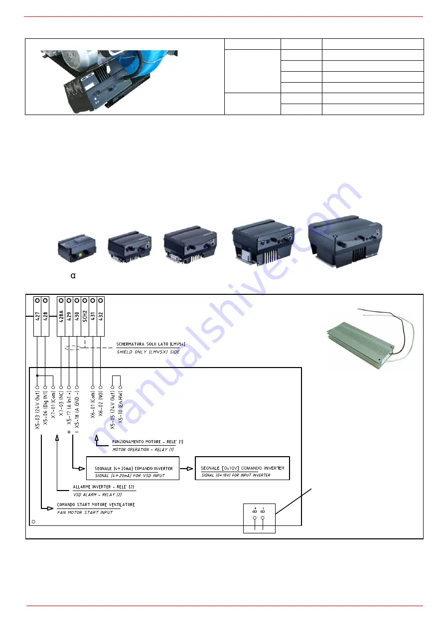
Terminal interface with Inverter
KOSTAL
Tipo
Modello
LMV5
XXXXX
M-. MD. xx. xx. x. x. xxx. EI.
XXXXX
M-. MD. xx. xx. x. x. xxx. EG.
XXXXX
MG. MD. xx. xx. x. x. xxx. EK.
XXXXX
MG. MD. xx. xx. x. x. xxx. ER.
LMV2x/3x
XXXXX
M-. MD. xx. xx. x. x. xxx. EB.
XXXXX
MG. MD. xx. xx. x. x. xxx. EC.
A
B
C
D
INVEOR M
INVEOR
Mx-xxxx-xxxx - LP02/LP04-...
LMV5 - HAGC31-CU01
LMV2x/3x
Connection to brake
resistors when provi-
ded
Braking resistances
Summary of Contents for H365X
Page 46: ......
Page 47: ......
Page 49: ...Siemens LMV5x Service Manual M12920CC rev 2 1 08 2017...
Page 56: ...8...
Page 60: ...12 2 2 LMV5x program structure...
Page 87: ...39...
Page 94: ......
Page 95: ......
Page 96: ...Note Specifications and data subject to change Errors and omissions excepted...
Page 98: ...Annex1 Example for motor cable...
Page 99: ......
Page 100: ...Annex 2 Example for sensor cable...
Page 101: ......
Page 102: ......
Page 106: ......


